
Installation Instructions
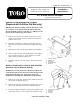


5. With the bed lowered, secure each cylinder rod end to the
appropriate slots in the bed mounting plates with a clevis
pin and lynch pin. Insert the clevis pin from outside of the
bed with the lynch pin toward the outside (Fig. 9). The rear
slots are for full bed installation and front slots are for 2/3-
bed installation.
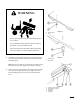
NOTE: Engine may need to be started to extend or retract
cylinders for alignment with holes. Keep fingers out!
NOTE: Plug the unused slot with a capscrew and nut to
prevent assembly errors.
6. Start the engine and the engage hydraulic lift lever to raise
the bed. Release the lift lever and turn off the engine.
Secure the raised bed with a hoist or block it to prevent it
from accidentally falling.
7. Install lynch pins to the inside ends of the clevis pins.
NOTE: If an automatic tail gate release has been installed
on the bed, make sure the front dump link rod has been
placed on the inside of the left side clevis pin before
installing the lynch pin.
8. Once cylinder installation is completed, the bed safety sup-
port can be used to prevent accidental lowering of the bed.
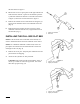
9. To use the bed safety support:
A. Raise the bed until the cylinders are fully extended.
B. Remove the bed support from the storage stud on top
of back rest support channel on the Workman (Fig.
10).
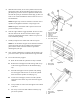
C. Push the bed support onto the cylinder rod, making
sure the support end tabs rest on end of the cylinder
barrel and on the cylinder rod end (Fig. 11).
D. To store the bed support, remove from the cylinder
and insert on the stud on top of the back rest support
channel.
E. Always install or remove the bed support from outside
of the bed.
F. Do not try to lower the bed with the bed safety sup-
port on the cylinder.
Figure 9
1. Bed mounting plate
2. Cylinder rod end
3. Clevis pin
4. Lynch pin
5. Rear slots (Full bed)
6. Front slots (2⁄3 bed)
Figure 10
1. Bed support
2. Storage stud
Figure 11
1. Bed support
2. Cylinder barrel
3. Bed
4