
Installation Instructions

1
All Rights Reserved
Printed in the USA
1994, 1995 by The Toro Company
8111 Lyndale Avenue South
Bloomington, MN 55420-1196
2/3 and Full Area Flatbed Side Kit
Workman
3000 Series Utility Vehicle
Model No. 07302–30001 & Up
Model No. 07322–30001 & Up
Form No. 3317–254 Rev A
Installation Instructions
1. Position bed on a table or bench, so top is facing up.
Position front panel on bed aligning mounting holes in
top and end of bed.
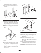
2. Loosely secure panel to top and front of bed with (5)
5/16–18 x 5/8” lg. capscrews and flange locknuts
(Fig. 2).
3. Position right and left side panels on bed and align
mounting holes. Loosely secure panels to top and sides
of bed and ends of front panel with side angles,
5/16–18 x 5/8” lg. capscrews and flange locknuts. (12)
capscrews and flange locknuts are required for
installation on a full area flatbed or (10) on a 2/3 area
flatbed. Position side angles as shown in figure 2. Do
not secure rear sides at this time.
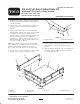
Note: When mounting side panels to full flatbeds with
serial numbers prior to 49999, each side of rear flange on
flatbed must be trimmed inward 5.33” as shown in
figure 1. Only trim outer flange to expose inner frame.
4. Loosely secure rear of each panel to rear of bed with a
5/16–18 x 1” lg. capscrew and flange locknut.
5.33”
2
1
Figure 1
1. Rear flange of bed 2. Right side of bed shown
5. Loosely secure rear flange of each panel to rear of bed
with a 5/16–18 x 3/4” lg. carriage bolt and flange
locknut.
6. While pushing panels toward center of bed, tighten all
assembled capscrews and flange locknuts starting at
rear and moving forward.
1
4
2
6
5
3
Figure 2
1. Flatbed
2. Front panel
3. Right side panel
4. Left side panel
5. Side angles 6. Rear flange of panel