Form No.
WARNING 1. This cab is designed to provide foul weather protection only. It does not provide protection from noise, exhaust fumes, chemicals or injury from collision, or other accidents. 2. Do not operate the machine in confined areas without proper ventilation. 3. Thoroughly check area of operation before using the machine. MAINTENANCE INSTRUCTIONS Periodically check all bolts to see that they are tight. If bolts become loose, failure of cab parts may occur.
CARTON CONTENTS #07337 Vinyl Enclosure for Workman MD series Key # Part # QTY Description 1 60046 1 Rear Post, RH (tagged) 2 60047 1 Rear Post, LH 3 60277 1 Front Post, RH (tagged) 4 60278 1 Front Post, LH 5 60048 1 Top Frame, RH (tagged) 6 60049 1 Top Frame, LH 7 60050 1 Door Post, RH (tagged) 8 60055 1 Top Cross Bar, (has tapped holes) 9 60051 1 Door Post, LH 10 60054 1 Rear Cross Bar 11 60057 1 Windshield 12 60056 4 Top Vinyl Support 13 60061 1 Rear Bow 14 60307 1 Dash Support Bracket, RH 15 60306B 1 Top
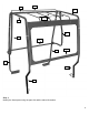
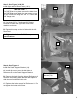
8 13 6 12 5 9 7 10 2 11 1 4 3 Step 1: Identify the frame parts using the parts list and the above illustration.
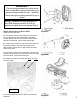
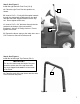
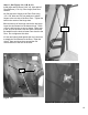
WARNING ! The following procedure to vent the fuel tank is required to prevent the build up of gasoline fumes inside the cab. Gasoline fumes can ignite causing serious injury or death. NOTE: Installation of this enclosure on any MDE electric unit and 2010 & up gasoline models does not require Step 2. Step 2; See Figure 2A, 2B, 2C & 2D: Install fuel tank vent hose. Figure 2A A. Remove the knob from the gearshift. Remove the four screws that hold the shifter plate to the shifter bracket.
Step 3; See Figure 3A & 3B: Install right and left Rear Posts (1 & 2). 1 IMPORTANT ! If a ROPS bar is in place remove the bolts from the ROPS bar and attach the rear posts on top of the ROPS bar using the 3/8” x 1” bolts and 3/8” flange nuts. A. Use three 3/8” x 1” bolts and 3/8” flange locknuts to fasten the right Rear Post to the machine as shown. B. Repeat this step on the left side with the left Rear Post. Figure 3A C. Tighten the bolts to R.O.P.S. torque specifications.
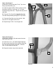
Step 5; See Figure 5: Install the right and left Front Post (3 & 4) A. Place the right Front Post into position as shown. 3 B. Insert a 5/16” x 1” bolt with flat washer inwards through the slotted tab at Reference B, the dash and then the Dash Support Bracket into the clip nut. Do not tighten at this time. C. Insert a 5/16” x 3/4” bolt down through the tab welded to the bottom of the post and the floorboard. Add a 5/16” flange lock nut. Do not tighten at this time. B D.
Step 7; See Figure 7: Install Door Post right and left (7 & 9), Top Cross Bar (8) and Rear Bow (13). 8 13 A. Hold the upper left Door Post in place over the two holes at the top. Insert two 1/4” x 2” bolts inwards through the holes. Repeat this step on the right side. B. Place the Top Cross Bar (tapped holes up) over the bolts protruding through the Top Frame. 9 C. Place the Rear Bow over the rear bolt. Add lock nuts. Do not tighten at this time. D. Repeat steps 7 B & C on the right side.
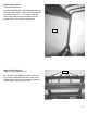
Step 9; See Figure 9: Install Windshield (11) A. Set the Windshield in place between the Front Posts and Top Frames. Place a 1/4” lock washer over each of four 1/4” x 1 1/2” bolts. Align the holes in the parts and insert the bolts into the tapped holes. Do not tighten at this time. 11 Figure 9 Step 10; See Figure 10: Install Top Vinyl Supports (12) 12 A. Place the vinyl supports in place as shown. Insert eight bolts down through the holes in the Supports, the Top Cross Bar and the Windshield.
Step 11; See Figure 11A, 11B, & 11C: Install right and left Doors (16 & 18), right and left Door Bottoms (17 & 19), Door Hinges, and Door Latches, A. Bolt two door Hinges to the Door Post using 1/4” x 5/8” bolts and 1/4” lock washers to attach hinges to the out side of the Door Post. Tighten the bolts in the center of the hinge slots. B. Insert the top of the hinge rod into the top hinge. Lower the door down into the bottom hinge. Place a Door Latch into the cut out as shown.
Step 12; See Figure 12A, 12B & 12C: Install Rubber Door Seal. Cab frame / Door alignment. IMPORTANT ! The ‘U’ shaped section of the rubber door seal will be applied to the edge of the door. The ‘tube’ shaped section of the rubber door seal should be between the doorframe and the cab frame. The use of a rubber mallet is recommended to gently seat the seal onto the doorframe. Figure 12A A. Cut two 63” pieces of rubber door seal.
Step 13; See Figure 13: Install adhesive hook Velcro® for Front Panel Vinyl. A. Cut a strip of adhesive hook Velcro® 45” long and apply to the lower front edge of the Windshield as indicated by the arrows. B. Cut two strips of adhesive hook Velcro® 17” long and apply to the forward side of the Front Post as indicated by the arrows. 45” 17” Figure 13 Step 14; See Figure 14A & 14B: Install adhesive hook Velcro®. Velcro® Strips 36” 7” A. Cut a strip of adhesive hook Velcro® 36” long and 7” long.
Step 15; See Figure 15: Install adhesive hook Velcro®. A. Cut two strips of adhesive hook Velcro® 17” long and 3” long and apply to the bottom side of both Top Frames as indicated by the arrows. Velcro® Strips 17” 3” NOTE: Start the strip about 1 1/2” from the mounting flanges of the Doorposts. Figure 15 Step 16; See Figure 16: Install adhesive hook Velcro®. A. Cut two 10” pieces of adhesive hook Velcro® and apply one piece to the outside of each rear post.
IMPORTANT ! Before continuing to STEP 17, check the position of the rear bow with Figure 14B and adjust accordingly. Step 17: Install Top / Rear Curtain A. Cut a 40” piece of adhesive hook Velcro® (DO NOT remove protective backing strip) Press the hooked strip onto the loop (soft pile) Velcro® located at the bottom edge of the Rear Curtain section of the panel. (window) B. Starting from the front, attach the front edge Velcro® to the two strips previously installed on the windshield frame in steps 14A. C.