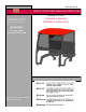
3362-440 REV B ROPS CERTIFIED DELUXE HARD CAB Model 07339 This cab is to be used on the following products and not to be used on any other units: WORKMAN® HD, HDX, HDX-D HDX 4WD, HDX-D 4WD This cab is manufactured for TORO by Jodale Perry Corporation Operators Manual Installation Instructions
Table of contents 1. Safety instructions……………………………………………3 2. Inspection guide……………………………………………..5 3. Safety labels and location…………………………………...6 4. Operation instructions………………………………………..7 5. Vehicle preparation…………………………………………..8 6. Cab installation……..….……………………………………..9 7. Parts list………………………………………………..…….12 8. Parts photos…………………………………………………13 9. Optional equipment…………………………………………13 10. To the purchaser…………………………………………….14 11.
SAFETY INSTRUCTIONS BEFORE OPERATING • Read and understand the contents of this material before operating the vehicle. Become thoroughly familiar with the controls, capabilities and proper use of equipment. • This cab fits all Workman® HD Series with serial numbers 29xxxxxxx or higher. • • DO NOT weld, cut, drill, or modify cab structure in any matter. • DO NOT allow children to operate vehicle. Do not allow adults to operate with out proper training. • Keep all shields and safety devices in place.
3362-141 Rev A SAFETY INSTRUCTIONS While operating • Verify capacity rating for the vehicle. Make sure that the GVW capacities are not exceeded. • Avoid sudden stops or sharp turns. • Always use safety belts. • Never allow riders on top of cab or in bed while operating vehicle. • Stay alert for hidden hazards and traffic. • Avoid sudden starts and excessive speeds. • Use extreme care when working around fences, ditches or on hillsides. • Check clearances carefully before driving under any objects.
ROPS Certified Cab, Roll Over Protection Structure Inspection Guide Cab has been certified to ISO 21299 ROPS certified cab like any other safety device needs to be periodically inspected to verify that the integrity of the devise has not been compromised though normal machine use, misuse, age degrading, modifications, or rollovers.
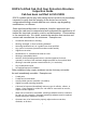
Replace decals immediately if damaged or missing. Part No: 117-4955 Located on right and left rear door post Warning - read the Operator’s Manual; wear the seat belt, avoid tipping the machine. Warning – wear hearing protection.
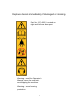
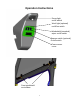
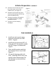
Operation Instructions Dome light on/off switch Work light (optional) no/off/on switch Windshield (standard) wiper on/off switch Beacon switch (optional) On/off switch Fuse access cover Front windshield vent sliders 7
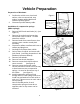
Vehicle Preparation Preparation of Workman 1. 2. Figure 1 Position the vehicle on a clean level surface, raise or remove bed, stop engine, engage parking brake and remove key from ignition. Disconnect positive battery cable. Retain: Cylinder Support Manual Tube Bolts Installation of compression springs (White springs) 3. 4. 5. 6. 7. 8. 9. 10. 11. 12. 13. Remove ROPS and retain bolts (6). (see Figure 1) Remove (4) socket head screws that secure each seat to vehicle. Lift both seats from vehicle.
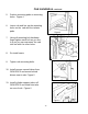
Vehicle Preparation continued 14. Remove lock nut and cap screw from form lower end of each stabilizer link. (see figure 4) Figure 4 15. Remove lock nut and cap screw securing each spring cradle along with the stabilizer links. 16. Reverse procedures 5 though 13, to install compression springs provided in the kit. 17. Remove Hood and unplug headlights. Cab Installation 1. Install rear cab mounts using fasteners retained from OEM ROPS. Figure1 2.
Cab Installation continued 5. Position mounting pads on mounting holes. Figure 4 6. Lower cab and line up the mounting holes on the cab with the isolator pads. 7. Using all mounting bolt hardware finger tighten each bolt as you line it up so you can maneuver the cab into line with the other holes. 8. Re-install seats. Figure 3 Figure 4 9. Tighten cab mounting bolts. 10. Install owners manual taken from OEM ROPS and mount behind drivers seat in cab. Figure 5 Figure 5 11.
Cab Installation continued 12. Run wire harness over tube and along front brace making sure that no moving parts rub against it. Figure 7 13. Plug red wire with spade connector with into the spare power lead coming out of the fuse block. Figure 8 Figure 7 14. Install ground wire onto ground block. Figure 8 15. Reinstall hood and reconnect headlights. 16. Reconnect the positive battery cable.
Standard Parts List Qty Description 2 Rear brackets (LH & RH) 2 Front Brackets 4 Bolt, 3/8” x 1” 4 Flat washer 3/8” 1 Lift bracket set 2 Bolt, 3/8” x 3” 6 Flange Lock Nuts, 3/8” 2 Plugs, 3/8” 4 Bolt, ½” x 3” 4 Washers rubber 4 3” Isolator pad rubber 4 Flange Lock Nut, 1/2” 4 Washers 9/16” ID 2 ½” OD 2 Heavy-duty springs (white) Standard Electrical Parts List Qty Description 1 20 AMP Fuse 12
Parts Photos Rear mount brackets, L&R Front mount Brackets, L&R 2” Lift Bracket set Optional equipment for Toro Workman HD Series Option Part No. Sliding door kit 07375 Solid door kit 07376 Heater kit 07374 Mirror kit 117-4830 Defrost fan (Available thru Jodale Perry) Work light kit (Available thru Jodale Perry) Rotating beacon (Available thru Jodale Perry) Jodale Perry Corporation 204-822-9100 www.jodaleperry.