Form No. 3358-750 Rev A 1/3 Platform Lift for Workman Vehicles Model No. 07344 Register at www.Toro.com.
Contents Introduction Introduction................................................................. 2 Safety ........................................................................... 3 Before Operating ................................................. 3 While Operating................................................... 3 Maintenance......................................................... 3 Safety and Instructional Decals ............................. 4 Setup.............................................
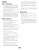
Safety • Always wear hard hat and eye protection while operating platform or while in area below platform. Before Operating • Never drop or throw articles from raised platform. • Read and understand the contents of this manual before operating the platform lift. Become familiar with all controls and know how to stop quickly.
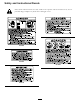
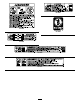
Safety and Instructional Decals Safety decals and instructions are easily visible to the operator and are located near any area of potential danger. Replace any decal that is damaged or lost.
93-3706 93-3704 93-3709 93-3708 93-3705 93-3707 5
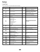
Setup Loose Parts Use the chart below to verify that all parts have been shipped. Procedure Description Use Qty.
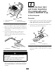
The 1/3 platform lift is designed to be used only with a Workman Vehicle and must be mounted with the wiring harness, level, decals, switches and all interlock switches installed. Important: If 1/3 Platform lift is to be installed on a 4 Wheel Drive Workman Vehicle with a serial number of 50001 & Up or a 2 Wheel Drive Liquid Cooled Workman Vehicle with a serial number of 60001 & Up, the base cover, part no. 93-3737, (Figure 2) must be removed from lift assembly and a 1/3 Cover Kit, part no.
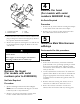
2 Remove the Seat, Skirt and Fender Assemblies (For models with serial numbers 240000001 & up) No Parts Required Procedure Figure 5 1. Center console cover 2. Seat frame 1. Position vehicle on a clean, level surface, stop engine, engage parking brake and remove key from ignition switch. Disconnect positive cable from battery. 3. Seat assembly 4. Skirt & fender assembly 2. Unscrew and remove all knobs from console levers and from the gear shift lever (Figure 7). 4.
4 Remove the hood (For models with serial numbers 240000001 & up) No Parts Required Procedure 1. Remove the (6) screws and nuts securing the bumper to the vehicle frame and remove the bumper. Figure 8 1. Console cover plate 2. Reservoir hose 2. Remove the (7) screws securing the front hood to the vehicle frame and remove the hood. 3. Seat 4. Shroud 4. Disconnect the reservoir hose from the radiator and plug or clamp it to retain coolant (Figure 8). Remove the operator shield from the ROPS. 5.
2. Loosely mount parking brake switch to vehicle console with (2) spacers, #10-24 screws, washers and nuts, as shown in Figure 10. Different length spacers and screws are used to mount switch level.
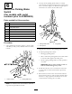
7 8 Mount the Parking Brake Switch (For models with serial numbers 240000001 & up) Mount Rear Level Switch Parts needed for this procedure: Parts needed for this procedure: 1 Parking brake switch 2 Screws 1 Jumper wire harness 1 Rear level switch bracket 1 Rear level switch w/harness Procedure 1. Remove locknuts securing hitch plate to rear axle (Figure 12). Loosely mount rear harness switch bracket to rear axle with locknuts removed. Procedure 1.
Note: To prevent lift scissor arms from expanding, pick up the platform lift from the bottom when positioning on frame. 9 3. Position lift onto frame aligning mounting holes with holes in frame. To Mount Lift In Forward Position On Vehicle Frame 4. Mount each side of lift to frame channels with a reinforcing plate and (2) 3/8-16 x 1" large flange head capscrews and flange nuts (Figure 15). Reinforcing plates to be used in rear mounting holes only.
Note: Lift may be installed on top of H.D. Hitch Frame Tubes. If lift is to be mounted on top of H.D. Hitch Frame Tubes, use next procedure. 8. Position lift onto frame aligning mounting holes with holes in mounting bracket. 9. Secure lift mounting brackets to lift with (4) 5/16-18 x 1" large flange head capscrews and flangenuts. Tighten all fasteners. 2. Remove the flange screw and locknut, shown in Figure 16, securing each side of engine frame to vehicle frame. 3.
12 Connect Wires No Parts Required Procedure 1. Plug rear harness into connector from front harness. 2. Connect ground wire from lift to engine ground. 3. Remove nut from positive battery clamp, insert positive wire from lift onto cable clamp screw and loosely secure with nut. Figure 18 1. H.D. Hitch frame tube 2. Hitch bracket 2. Secure lift mounting brackets to lift with (4) 5/16-18 x 1" large flange head capscrews and flangenuts. Position brackets as shown in Figure 19. 3.
4. Reinstall positive battery cable to battery. 5. Slide rubber boot over positive terminal to prevent possible short-out from occurring. 14 Mount Circular Bubble Level Parts needed for this procedure: Figure 22 1 Circular Bubble Level 1. No—Step decal Procedure 2. Affix a "No Step" decal to top of each fuel tank mounting strap, as shown in Figure 22. Affix circular level to top of console cover positioning as shown in Figure 21. Figure 21 1. Circular level 2.
Product Overview Controls Up Button Press "UP" button to raise lift (Figure 23). Down Button Press "DOWN" button to lower lift (Figure 23). Key Switch Figure 24 Rotate key switch to authorize use of lift. Remove key from lift pendant control switch to prevent operation when unattended. (Figure 23). 1. Emergency lowering valve knob Figure 23 1. Pendant control 2. UP button 3. DOWN button 4.
Operation Maximum air pressure in front tires is 20 psi Maximum air pressure in rear tires is 32 psi for 23" tires and 18 psi for 24" tires. Check Oil Level The lift reservoir is filled at the factory with DTE 13 hydraulic oil. Check level before lift is first operated and every 8 hours or daily, thereafter. Capacity of system is 1.5 qt. 1. Position the vehicle on a level surface. 2. Raise lift and install safety blocks. Refer to the Installing Safety Blocks section and the Operation chapter.
Operating the Lift The 1/3 platform lift is designed to be used only with a Workman Vehicle and must be mounted with the wiring harness, level, decals, switches and all interlock switches installed. Improper operation of platform lift may cause serious personal injury or death. To reduce risk to operator and bystanders: Figure 26 2. Retaining pin 1. Safety block • Read and understand all safety instructions in Workman and Platform Lift Operator’s Manuals and warning labels. 7.
Loss of control or tip-over will result if vehicle is moved with platform in raised position and may cause serious personal injury to operator or bystanders. • Never move vehicle while platform is raised. • Always apply parking brake before raising platform. Wheel chock use is recommended. • Never release parking brake while platform is raised. • Check safety interlocks before each use of platform. See operator’s manual for safety interlock check instructions. • Never bypass safety interlocks.
Contact between non-insulated platform lift and power lines will cause electrocution. Contact with moving scissor arms can cause personal injury. • Electrocution will cause serious personal injury or death. • Stand clear of scissor arms while platform is moving. • Never use platform lift near power lines. • Make sure area is clear of bystanders before lowering platform. • Never allow platform lift to touch power lines. • Never work under raised platform without lift safety blocks installed.
Falling or jumping from raised platform will cause personal injury. Tip-over of Workman Vehicle while platform is raised will result in personal injury to operator and/or bystanders. • Secure both handrail snap chains across opening before raising platform. • Always park vehicle on firm, level surface before raising platform. • Never pull on objects while reaching from raised platform. • Never exceed 5 degree maximum angle of operation.
Maintenance is stored in a location where temperatures are extremely high, the battery will run down more rapidly than if the machine is stored in a location where temperatures are cool. Check Safety Circuits The electrical safety circuits of the lift require the vehicle to be parked on a slope of less than 5 degrees and parking brake to be engaged in order to activate the lift circuit. 2. Keep top of battery clean by washing periodically with a brush dipped in ammonia or bicarbonate of soda solution.
Schematics (Rev.