
Installation Instructions


6
MounttheParkingBrake
Switch
(Formodelswithserial
numberspriorto230999999)
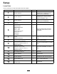
Partsneededforthisprocedure:
1
Capscrew#10-24x1"
1
Locknut#10-24
1
ParkingBrakeSwitch
1
Spacer-Long
1
Spacer-Short
1
Screw#10-24x2-1/4"
1
Screw#10-24x2"
2
Washer#10
2
Nut#10-24
Procedure
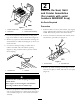
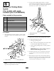
1.UsingdimensionsshowninFigure9,locate,mark
anddrill(2).218"(7/32")diameterholesinvehicle
console.
Figure9
1.Vehicleconsole2.Parkingbrakelever
Note:OnVehicleswithserialnumbers50001&
Up,holesareprovidedinconsole.
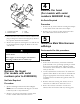
2.Looselymountparkingbrakeswitchtovehicle
consolewith(2)spacers,#10-24screws,washersand
nuts,asshowninFigure10.Differentlengthspacers
andscrewsareusedtomountswitchlevel.
Figure10
1.Parkingbrakeswitch3.Longspacer
2.Shortspacer
3.Plugharnessconnectorintoparkingbrakeswitch.
4.Toadjustparkingbrakeswitch:
•Disengageparkingbrake.
•Moveswitchintoparkingbrakeleveruntilswitch
isactivated,thentightenmountingnuts.
•Slowlyengageparkingbraketocheckoperation
ofswitch.
Important:Donotmoveswitchtocloseto
leverasswitchdamagemayoccur.
5.Installwireharnesscoveroverharness’andsecure
toundersideofvehiclewithfastenerspreviously
removed.
6.Routeharnesstowardvalveonleftframechannel.
Secureharnessrelaystosideofframechannelwitha
#10-24x1"largecapscrewandlocknutoruseone
ofthefastenerssecuringvalvetoframe.
10