Form No. 3361-472 Rev A 1/3 Platform Lift for Workman Heavy-Duty Utility Vehicle Model No. 07344—Serial No. 2900000001 and Up To register your product or download an Operator's Manual or Parts Catalog at no charge, go to www.Toro.com.
Contents Introduction Introduction................................................................. 2 Safety ........................................................................... 3 Before Operating ................................................. 3 While Operating................................................... 3 Maintenance......................................................... 3 Safety and Instructional Decals ............................. 4 Setup.............................................
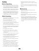
Safety • When raising platform be alert for overhead obstructions which could cause eye, head or crushing injuries. Before Operating • Stand clear of scissor arms while platform is moving. • Read and understand the contents of this manual before operating the platform lift. Become familiar with all controls and know how to stop quickly. A replacement manual is available at www.Toro.com. • Make sure area is clear of bystanders before lowering platform.
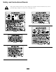
Safety and Instructional Decals Safety decals and instructions are easily visible to the operator and are located near any area of potential danger. Replace any decal that is damaged or lost.
93-3706 93-3704 93-3709 93-3708 93-3705 93-3707 5
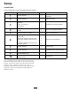
Setup Loose Parts Use the chart below to verify that all parts have been shipped. Procedure 1 2 3 4 5 6 7 8 9 10 Description Use Qty. No parts required – Remove the seat, shroud and fender assemblies No parts required – Remove the hood Main Wire Harness w/ Relays Cable Tie Screw, 1/4 x 3/4 inch Nut, 1/4 inch Fuse Parking brake switch Screws Rear level switch bracket Rear level switch w/ harness Reinforcing Plate Spacer tube Flange HD. Capscrew, 3/8-16 x 3 inch Flange HD.
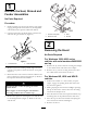
1 Remove the Seat, Shroud and Fender Assemblies No Parts Required Procedure 1. Position vehicle on a clean, level surface, stop engine, engage parking brake and remove key from ignition switch. Disconnect positive cable from battery. Figure 3 2. Unscrew and remove all knobs from console levers and from the gear shift lever (Figure 2). 1. Console cover plate 2. Reservoir hose 3. Seat 4.
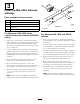
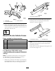
3 Install the Main Wire Harness w/Relays Parts needed for this procedure: 1 Main Wire Harness w/ Relays 7 Cable Tie 2 Screw, 1/4 x 3/4 inch 2 Nut, 1/4 inch 1 Fuse Figure 4 1. Relays For Workman 3000–4000 series vehicles with serial numbers 240000001 and up For Workman HD, HDX and HDX-D vehicles 1. Insert end of wire harness, with male and female spade terminals on it, up through opening in vehicle floor board. 1.
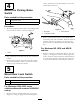
loosely mount the level switch bracket to rear axle with locknuts removed. 4 Mount the Parking Brake Switch Parts needed for this procedure: 1 Parking brake switch 2 Screws Procedure 1. Mount the parking brake switch to the parking brake mount with two screws as shown in Figure 5. Figure 6 1. Hitch plate 2. Level switch bracket 3. Switch harness 2. Route switch harness forward, along differential lock cable to left side of machine. Harness must not interfere with any hot (exhaust) or moving parts.
Figure 8 1. Hitch frame extension tube Figure 7 1. Hitch plate 2. Level switch bracket 2. Locate and remove the threaded insert from the mounting hole in left and right vehicle frame channels, as shown in Figure 9. 3. Switch harness 2. Route switch harness forward, along shift cable to left side of machine. Harness must not interfere with any hot (exhaust) or moving parts. Secure harness to shift cable with cable ties.
2. Locate and remove the threaded insert from the mounting hole in left and right vehicle frame channels, as shown in Figure 9. Figure 12 1. Vehicle frame channel 3. Position a spacer tube onto each frame channel aligning mounting holes with holes in frame (Figure 13). Figure 10 1. Lift 2. Threaded insert 2. Reinforcing plate 4. Mount each side of lift to frame channels with a reinforcing plate and (2) 3/8-16 x 1 inch large flange head capscrews and flange nuts (Figure 10).
inch flange head capscrews and flange nuts. Use the (2) 3/8-16 x 3 inch flange head capscrews in front mounting holes (Figure 13). 2. Reinstall shroud, seats, seat frame and console cover plate, if applicable. 3. Reinstall overflow tube to radiator. Check coolant level and replenish, if required. 7 4. Reinstall positive battery cable to battery. 5. Slide rubber boot over positive terminal to prevent possible short-out from occurring. Connect Wires 9 No Parts Required Procedure 1. 2. 3. 4.
10 Install Decals Parts needed for this procedure: 1 Operation Decal 2 No Step Decal 1 G01021 1 Figure 17 1. No—Step decal For Workman 3000–4000 series vehicles with serial numbers 240000001 and up 1. Affix operation decal to top of console cover positioning as shown in Figure 15. 2. Affix a "No Step" decal to top of each fuel tank mounting strap, as shown in Figure 16. Figure 16 1. No—Step decal For Workman HD, HDX and HDX-D vehicles 1.
Product Overview Controls Up Button Press "UP" button to raise lift (Figure 18). Down Button Press "DOWN" button to lower lift (Figure 18). Key Switch Figure 19 Rotate key switch to authorize use of lift. Remove key from lift pendant control switch to prevent operation when unattended. (Figure 18). 1. Emergency lowering valve knob Figure 18 1. Pendant control 2. UP button 3. DOWN button 4.
Operation Check Tire Pressure Check Oil Level Check tire pressure every 8 hours or daily to assure proper levels. Refer to the vehicle operator’s manual for proper tire inflation specification. The lift reservoir is filled at the factory with DTE 13 hydraulic oil. Check level before lift is first operated and every 8 hours or daily, thereafter. Capacity of system is 1.5 qt. Installing Safety Blocks 1. Position the vehicle on a level surface. 1. Position the vehicle on a level surface. 2.
7. Rotate safety blocks 90 degrees in channel and secure to ends of lift frame with retaining pins (Figure 22). Improper operation of platform lift may cause serious personal injury or death. To reduce risk to operator and bystanders: • Read and understand all safety instructions in Workman and Platform Lift Operator’s Manuals and warning labels. • Never use a platform lift without proper training and authorization.
Operation of platform lift without parking brake engaged can result in tip-over and personal injury. Contact between non-insulated platform lift and power lines will cause electrocution. • Electrocution will cause serious personal injury or death. • Always apply parking brake before operating platform lift. The use of wheel chocks is recommended. • Never use platform lift near power lines. • Never allow platform lift to touch power lines. • Do not release parking brake while platform lift is raised.
Contact with moving scissor arms can cause personal injury. Falling or jumping from raised platform will cause personal injury. • Stand clear of scissor arms while platform is moving. • Secure both handrail snap chains across opening before raising platform. • Make sure area is clear of bystanders before lowering platform. • Never pull on objects while reaching from raised platform. • Never work under raised platform without lift safety blocks installed.
Tip-over of Workman Vehicle while platform is raised will result in personal injury to operator and/or bystanders. • Always park vehicle on firm, level surface before raising platform. • Never exceed 5 degree maximum angle of operation. • Never raise platform if bubble level indicator is outside recommended operating range. • Never raise platform if one or more vehicle tires under inflated; check tire pressure daily. • Never pull on objects while reaching from raised platform.
Maintenance Battery Care 1. Battery electrolyte level must be properly maintained and the top of the battery kept clean. If the machine is stored in a location where temperatures are extremely high, the battery will run down more rapidly than if the machine is stored in a location where temperatures are cool.
Warning CALIFORNIA Proposition 65 Warning Battery posts, terminals, and related accessories contain lead and lead compounds, chemicals known to the State of California to cause cancer and reproductive harm. Wash hands after handling. Charging the battery produces gasses that can explode. Never smoke near the battery and keep sparks and flames away from battery. Battery terminals or metal tools could short against metal components causing sparks.
Schematics Electrical Schematic (Rev.
Notes: 23
Toro General Commercial Products Warranty A Two-Year Limited Warranty Conditions and Products Covered The Toro Company and its affiliate, Toro Warranty Company, pursuant to an agreement between them, jointly warrant your Toro Commercial Product (“Product”) to be free from defects in materials or workmanship for two years or 1500 operational hours*, whichever occurs first. This warranty is applicable to all products with the exception of Aerators (refer to separate warranty statements for these products).