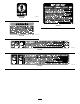
Form No. 3392-713 Rev B 1/3 Area Platform Lift Workman® Heavy-Duty Utility Vehicle Model No. 07347—Serial No. 315000001 and Up Register at www.Toro.com.
Contents WARNING CALIFORNIA Proposition 65 Warning This product contains a chemical or chemicals known to the State of California to cause cancer, birth defects, or reproductive harm. Use of this product may cause exposure to chemicals known to the State of California to cause cancer, birth defects, or other reproductive harm. Safety ....................................................................... 3 Before Operating ................................................ 3 While Operating.................
Safety • Do not exceed the capacity of the platform lift; 1 Before Operating • Always wear a hard hat and eye protection while person with the equipment should not to exceed 272 kg (600 lb). operating the platform or while in area below the platform. • Read and understand the contents of this manual before operating the platform lift. Become familiar with all controls and know how to stop the machine quickly. A replacement manual is available at www.Toro.com.
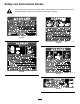
Safety and Instructional Decals Safety decals and instructions are easily visible to the operator and are located near any area of potential danger. Replace any decal that is damaged or missing.
decal93-3709 93-3709 decal93-3711 93-3711 decal93-3710 93-3710 decal93-3705 93-3705 decal93-3707 93-3707 5
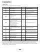
Installation Loose Parts Use the chart below to verify that all parts have been shipped. Procedure Description Use Qty. 1 2 No parts required – Prepare to install the kit. No parts required – Remove the center console, seat shroud, and seat assemblies. 3 No parts required – Remove the CVT cooling duct (HDX-Auto only).
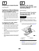
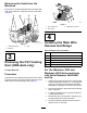
1 2 Preparing to Install the Kit Removing the Center Console, Seat Shroud, and Seat Assemblies No Parts Required For Workman 3000 and Workman 4000 Series machines with Serial Numbers 240000001 and Up 1. Position the machine on a clean, level surface, shut off the engine, engage the parking brake, and remove the key from the ignition switch. 2. Disconnect the positive cable from the battery. 3. Remove the 6 screws and nuts securing the bumper to the machine frame and remove the bumper. 4.
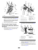
g023165 Figure 3 1. Screw 4. g024571 Figure 4 2. Cover plate Disconnect the reservoir hose from the radiator and plug or clamp it to retain coolant (Figure 3). Note: If your machine is equipped with a black pressurized tank, leave the hoses connected and lift the tank off the shroud. 5. 1. Brake lever 5. Transmission lever (L position) knob 2. Hydraulic-lift lever knob 6. Hydraulic-lift lock (locked position — left) 3. Speed-range lever knob 7. Speed-range lever (A position) 4.
Removing the Seats from the Machines Remove the 8 socket-head bolts that secure the seat rails of the seat to the chassis and remove the seats (Figure 6). g024791 Figure 7 1. CVT intake hose 2. Hose clamp 3. Intake-tube connector 4 Installing the Main Wire Harness and Relays g023164 Figure 6 1. Socket-head bolts 2. Seat rail 3.
6. Remove the fasteners securing the wire harness cover to the underside of the machine floor and remove the cover. 5. Remove the fasteners securing the wire harness cover to the underside of the machine floor and remove the cover. 7. Route the wire harness rearward to the console area. 6. Route the wire harness rearward to the console area. Note: The harness must not interfere with any hot (exhaust) or moving parts. Note: The harness must not interfere with any hot (exhaust) or moving parts. 8.
g028255 Figure 10 1. Target icon on the switch 8. 2. Gap (between 0.06 and 0.1 inch) Ensure that the gap between the head of the clevis pin and the switch should be between 0.06 and 0.1 inch. Note: If the gap is not correct, adjust the head of the pin by moving the position of the washers installed in steps 3 and 4. g028254 Figure 9 1. Carriage bolt 4. Bracket 2. Plate 3. Switch 5. Nut 2. 9.
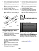
Mounting the Parking Brake Switch Workman Models with a Manual Transmission 1. Mount the parking brake switch to the parking brake mount with 2 screws as shown in Figure 11. g016822 Figure 12 1. Hitch plate g007162 2. Figure 11 1. Switch 3. 2. Plug the switch wire connector into the lift wire connector harness. 3. Remove the loop back connector from the machine wire harness labeled 1/3 lift. 4. 2.
bracket to the rear axle with the capscrews previously removed. 8 Note: Position the washers between the hitch plate and axle. 3. Tighten the 4 capscrews. 4. Route the switch harness forward, along shift the cable to the left side of the machine. Mounting the Lift onto the Machine Frame Note: The harness must not interfere with any Parts needed for this procedure: hot (exhaust) or moving parts. 5. Secure the harness to the shift cable with cable ties.
Note: To prevent the lift scissor arms from 9 expanding, pick up the platform lift from the bottom when positioning it on the frame. 3. Position the lift onto the frame, aligning the mounting holes with the holes in the frame (Figure 16). Connecting the Wire Harness and Battery Parts needed for this procedure: 1 Battery cable with boot 1 Negative battery cable Procedure g006700 Figure 16 1. Lift 4. 2.
10 Mounting the Bubble Level Indicator Parts needed for this procedure: 1 Bubble level indicator Procedure Affix the bubble level indicator to the top of the console cover as shown in Figure 18. g017228 Figure 17 1. Positive lift wire 3. Red wire from front harness 2. Positive battery cable clamp 8. Ensure that the wire is clear of all hot or rotating parts. 9. Secure the harness with cable ties. 10. Install the positive battery cable to the battery. 11.
For Workman HD, HDX, HDX-D, and HDX-Auto Machines 11 Installing the Decals 1. Affix the operation decal to the top of the console cover as shown in Figure 18. 2. Affix the no-step decals to the top of the radiator as shown in Figure 20. Parts needed for this procedure: 1 Operation decal 2 No-step decal For Workman 3000 and Workman 4000 Series Machines with Serial Numbers 240000001 and Up 1. 2. Affix the operation decal to the top of the console cover as shown in Figure 18.
Key Switch Product Overview Rotate the key switch to authorize the use of the lift. Remove the key from the lift pendant control switch to prevent operation of the lift whenever the machine is left unattended (Figure 21). Controls Emergency Lowering Valve Knob Push the blue knob inward, rotate it 90 degrees counterclockwise, and pull it out to activate the emergency lowering valve (Figure 22).
Checking the Tire Pressure Operation Check the tire pressure every 8 hours or daily to ensure proper levels. Checking the Oil Level Refer to the machine Operator’s Manual for tire inflation specification. Capacity: 1.5 US qt The lift reservoir is filled at the factory with 5W30 oil. Check the level before the lift is first operated and every 8 hours or daily, thereafter. Engaging Safety Locks 1. Position the machine on a level surface. 1. Position the machine on a level surface. 2.
Operating the Lift The 1/3 platform lift is designed to be used only with a Workman machine and must be mounted with the wire harness, level, decals, switches, and all the interlock switches installed. DANGER Improper operation of the platform lift may cause serious personal injury or death. To reduce risk to you and bystanders, do the following: • Read and understand all the safety instructions in the Workman and Platform Lift Operator's Manuals and warning labels.
DANGER DANGER If you move the vehicle with the platform in the raised position, a loss of control or tip-over will result, causing possible serious personal injury to you or bystanders. Contact between the non-insulated platform lift and power lines will cause electrocution, causing serious injury or death. • Never use the platform lift near power lines. • Never move the machine while the platform is raised. • Never allow the platform lift to touch power lines.
Emergency Lowering 1. Operating Tips Push the blue knob inward, rotate it 90 degrees counterclockwise, and pull it out to activate the emergency lowering valve (Figure 22). The electrical system, battery, and hydraulic lift cylinder are not designed for continuous use. Allow approximately 1-1/2 to 2 minutes between lift operations to maintain the operating temperature. DANGER Frequent use without the engine running or idling, between lift use, may discharge the battery.
Maintenance Testing the Rear Axle-Level Switch 1. Checking the Safety Circuits Note: The slope can be a floor jack, mound of material, or a small hill. The electrical safety circuits of the lift require the machine to be parked on a slope of less than 5 degrees, the parking brake to be engaged, and the ignition key off to activate the lift circuit. 2. Engage the parking brake and chock the wheels. 3. With the engine off, rotate the ignition key switch to the ON position. 4.
Maintaining the Battery WARNING Service Interval: Every 50 hours CALIFORNIA Proposition 65 Warning Battery posts, terminals, and related accessories contain lead and lead compounds, chemicals known to the State of California to cause cancer and reproductive harm. Wash hands after handling. The battery electrolyte level must be properly maintained and the top of the battery kept clean.
Notes:
Notes:
Notes:
Declaration of Incorporation The Toro Company, 8111 Lyndale Ave. South, Bloomington, MN, USA declares that the following unit(s) conform(s) to the directives listed, when installed in accordance with the accompanying instructions onto certain Toro models as indicated on the relevant Declarations of Conformity. Model No. 07347 Serial No.
The Toro Warranty A Two-Year Limited Warranty Conditions and Products Covered The Toro Company and its affiliate, Toro Warranty Company, pursuant to an agreement between them, jointly warrant your Toro Commercial product (“Product”) to be free from defects in materials or workmanship for two years or 1500 operational hours*, whichever occurs first. This warranty is applicable to all products with the exception of Aerators (refer to separate warranty statements for these products).