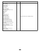
Form No. 3426-292 Rev A Heater Kit Liquid-Cooled Workman® MD/HD Utility Vehicle Model No. 07349—Serial No. 315000001 and Up Model No. 07349—Serial No. 316000001 and Up Model No. 07349—Serial No. 400000000 and Up Installation Instructions Loose Parts Use the chart below to verify that all parts have been shipped.
Description Heater-mount assembly Heater assembly Straight fitting (3/8 inch) U-bolt (3/8 inch) Locknut (3/8 inch) Hose channel Heater-control mount Heater-control panel Self-tapping screw (#12 x 1/2 inch) 90° heater hose Heater valve R-clamp Gasket Cap fitting (3/4 inch) Tee fitting (1 inch) Heater-control mount Hose clamp (1/2 inch) Hose clamp (7/8 inch) Hose clamp (3/4 inch) Coolant hose (3/8 x 12 inches) Coolant hose (5/8 x 124 inches) Heater-cable control (36 inches) Corrugated conduit (7/8 x 96 inches
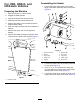
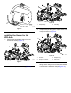
For HDX, HDX-D, and HDX-Auto Vehicles Assembling the Heater 1. Loosely attach the elbow hose to the bottom fitting of the heater assembly with a hose clamp (Figure 2). Preparing the Machine 1. Park the machine on a level surface. 2. Engage the parking brake. 3. Shut off the engine and remove the key. 4. Raise the bed and insert the safety bar. 5. Remove the battery cover and disconnect the positive battery cable. 6. Drain the engine coolant; refer to the Operator’s Manual. 7.
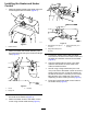
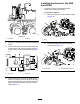
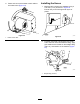
Installing the Heater and Heater Control 1. Attach the heater bracket to the heater using the screws supplied with the heater (Figure 3). g023414 Figure 5 g018041 Figure 3 1. Self-tapping screw (#12 x 1/2 inch) 1. Heater bracket 2. 2. Flange-head bolt (5/16 x 3/4 inch) Attach the heater and bracket assembly onto the front frame tube using the U-bolts and flange nuts (Figure 4). g017984 Figure 4 1. U-bolt 3. R-clamp 2. Flange nut 3.
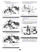
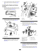
g269459 Figure 8 1. Adapter fitting 2. Tee fitting g017986 Figure 6 3. 1. Heater-control cable Install the temperature switch and the hose (3/8 inch) and adapter fitting (5/8 inch) with hose clamps as shown in Figure 9. Installing the Hoses for the HDX-Auto 1. Remove the temperature switch from the thermostat housing (Figure 7). g268910 Figure 9 g268912 1. Tee fitting 3. Adapter fitting 2. Temperature switch 4. Hose clamp Figure 7 4. 1. Temperature switch 2.
Installing the Hoses for the HDX and HDX-D 1. Remove the plug or temperature switch depending on the type of engine. For gasoline engines: A. Remove the plug in the thermostat housing (Figure 12). g025970 g268914 Figure 10 1. Short hose Figure 12 2. Tee fitting 1. Plug 5. Cover the hoses (5/8 inch) with split corrugated tubing. 6. Connect the long hose to the heater valve with a hose clamp, and route it under the machine, over the axel, and to the straight fitting (Figure 11). B.
For diesel engines: A. 2. Remove the temperature switch from the thermostat housing (Figure 14). Cut the lower radiator hose approximately 89 mm or 3-1/2 inches from the center line of the hose at the 90° bend (Figure 17). g017988 Figure 17 g268920 Figure 14 1. Tee fitting 2. Lower radiator hose 1. Temperature switch B. Install a tee fitting (Figure 15). C. Install the temperature switch (Figure 15). 3.
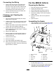
For the MDX-D Vehicle Connecting the Wiring 1. Connect the pink wire from the heater wire harness to an open lead on the fuse block. Preparing the Machine If there is not an open fuse slot, install a new fuse block. Install the fuse in the open slot corresponding to the power lead you use. 2. 1. 2. 3. 4. 5. Connect the black wire from the heater wire harness to the ground block. Finishing and Checking the Installation 1. Tie all the hoses and wires away from sharp edges and moving parts. 2.
4. Connect the white fill tee, gasket, and cap to the upper heater hose with a hose clamp (Figure 19). Installing the Heater and Heater Control 1. Drill a hole (5/16 inch) in the glove box 216 mm or 8-1/2 inches from the left and 38 mm or 1-1/2 inches from the bottom (Figure 20). g018025 g018003 Figure 20 2. Figure 22 Attach the heater bracket to the heater using the screws supplied with the heater (Figure 21). 1. R-clamp 3. U-frame 2. Flange nut 4. U-bolt 4.
8. Installing the Hoses Route and connect the heater-control cable to the heater valve (Figure 24). 1. Mark and drill 2 holes in the seatbase using a hole saw (1 inch) as shown in Figure 25. Ensure that you drill through both layers of plastic. g017986 Figure 24 g017990 Figure 25 1. Heater-control cable 2. Put down a drip pan.
3. Connecting the Wiring Cut the lower radiator hose about 54 mm or 2-1/8 inches from the end of the hose going into the radiator (Figure 27). 1. Connect the pink wire from the heater wire harness to an open lead on the fuse block. If there is not an open fuse slot, install a new fuse block. Install the fuse in the open slot corresponding to the power lead you use. 2. Connect the black wire from the heater wire harness to the ground block. Finishing and Checking the Installation 1.
Notes:
Notes:
Declaration of Incorporation Model No. Serial No. Product Description Invoice Description General Description Directive 07349 315000001 and Up, 316000001 and Up, and 400000000 and Up and Up Heater Kit, Liquid-Cooled Workman MD/HD Utility Vehicle MD/HD HEATER KIT-LIQUID COOLED ENGINES Utility Vehicle Accessory 2006/42/EC, 2000/14/EC Relevant technical documentation has been compiled as required per Part B of Annex VII of 2006/42/EC.
EEA/UK Privacy Notice Toro’s Use of Your Personal Information The Toro Company (“Toro”) respects your privacy. When you purchase our products, we may collect certain personal information about you, either directly from you or through your local Toro company or dealer.
The Toro Warranty A Two-Year Limited Warranty Conditions and Products Covered The Toro Company and its affiliate, Toro Warranty Company, pursuant to an agreement between them, jointly warrant your Toro Commercial product (“Product”) to be free from defects in materials or workmanship for two years or 1500 operational hours*, whichever occurs first. This warranty is applicable to all products with the exception of Aerators (refer to separate warranty statements for these products).