Form No. 3371-995 Rev A Electric Bed Lift Kit 2011 and After Workman® MDE Utility Vehicle Model No. 07382—Serial No. 312000001 and Up Installation Instructions Safety Safety and Instructional Decals Safety decals and instructions are easily visible to the operator and are located near any area of potential danger. Replace any decal that is damaged or lost. 120–5060 © 2011—The Toro® Company 8111 Lyndale Avenue South Bloomington, MN 55420 Register at www.Toro.com.
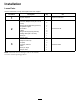
Installation Loose Parts Use the chart below to verify that all parts have been shipped. Procedure 1 2 3 Description Use Qty.
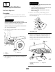
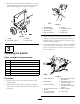
WARNING 1 A raised box could fall and injure persons that are working beneath it. • Always use the prop rod to hold the box up before working under the box. • Remove any load material from the box before raising it. Preparing the Machine No Parts Required Procedure 4. Remove a short battery cable linking any two batteries in the battery bank to remove power from the system (Figure 2). 1. Position the machine on a level surface. Set the parking brake, turn the ignition off, and remove the key.
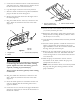
(3/8 inch) while aligning the mounting holes with the holes in the battery tray (Figure 5). 2 Installing the Bed Lift Parts needed for this procedure: 1 Lift bracket, upper 4 Pan-head, Phillips screw (3/8 x 2-1/2 inches) 4 Flange locknut (Whiz lock) (3/8 inch) 1 Lift cylinder support 1 Lift actuator 2 U-bolts 6 Flange locknut (Nylock) (3/8 inch) 2 Carriage bolts (3/8 x 3/4 inch) 1 Clevis pin 1 Hair pin cotter Figure 5 Procedure 1.
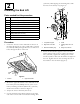
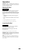
6. Mount the bottom end of the lift actuator to the lift cylinder support with a clevis pin and hair pin cotter. Position the components as shown in Figure 6. 2 Figure 7 1. Solenoid plate 5. Nut, #10 2. Solenoid, existing 6. Accessory harness 3. Solenoid, new 7. Large posts 4. Bolt, #10 x 3/4 inch 8. Small posts g017661 Figure 6 1. Actuator 3. Clevis pin 2. Lift cylinder support 4. Hair pin cotter 3. Attach the accessory harness to the solenoid. Connect a large ring to each large post.
5. Locate the box lift kit connector on the main harness and remove the cap. Attach accessory harness to box lift kit connector wire from main harness. 2 6. Cap 48v output connector on accessory harness. 1 7. Place the switch connector into position behind the plug in the dash as shown in Figure 8. 8. Remove the plug from the hole in the right side of the dash (Figure 9). G017535 9. Plug the switch into the accessory connector in the dash. Insert the switch into the hole in the dash (Figure 9).
Operation Important: When a ratcheting noise is heard, the box lift is completely extended or retracted. Do not continue pressing the switch. Raising the Bed WARNING Driving the vehicle with the cargo box raised may cause the vehicle to tip or roll easier. The box structure may become damaged if the box is raised for an extended period of time while operating the vehicle. • Only operate the vehicle when the cargo box is down. • After a load has been dumped, lower the cargo box. 1.
The Toro Total Coverage Guarantee A Limited Warranty Conditions and Products Covered The Toro Company and its affiliate, Toro Warranty Company, pursuant to an agreement between them, jointly warrant your Toro Commercial product (“Product”) to be free from defects in materials or workmanship for two years or 1500 operational hours*, whichever occurs first. This warranty is applicable to all products with the exception of Aerators (refer to separate warranty statements for these products).