
Installation Instructions

Form No. 3315-479 Rev B
Auxiliary Power Unit Kit for Heavy Duty
Workman
Model No. 07401
Model No. 07402
Installation Instructions
Installation
Loose Parts
Use the chart below to verify that all parts have been shipped.
Step
Description
Qty.
Use
1
No parts required
–
Disassemble the components.
Drive shaft w/pulley
1
Locknut
1
Long spacers
2
Cap screws
4
2
Flat washers
4
Assemble the components.
Step
1
Disassembling the
Components
No Parts Required
Procedure
1. R emo v e the 1/3 bed, if the mac hine is so
equipped. Raise the full bed and secure it with
the safety suppor t.
2. R emo v e the 2 cap screws , w ashers , and spacers
securing the front dri v e shaft coupling to the
engine pulley .
3. R emo v e the 2 cap screws , w ashers , and spacers
securing the rear dri v e shaft coupling to the
jac k shaft assembly .
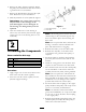
Figure 1
1. Engine pulley 5. Jack shaft drive pulley
2. Drive shaft 6. Hydraulic pump drive belt
3. Jack shaft assembly 7. Woodruff key
4. Jack shaft support
4. Loosen the idler pulley tensioning the h y draulic
pump dri v e belt and remo v e the belt from the
jac kshaft dri v e pulley .
5. R emo v e the loc kn ut and w asher securing the
jac k shaft dri v e pulley to the jac k shaft. R etain
the w asher for re-installation.
© 1993, 2005—The Toro® Company
8111 Lyndale Avenue South
Bloomington, MN 55420
Register at www.Toro.com. Original Instructions (EN)
Printed in the USA.
All Rights Reserved