(MODEL NO. 0740350001 & UP FORM NO. 3319592 ~ OPERATORS MANUAL . SAFETY INSTRUCTIONS 120 VOLT AC GENERATOR for Workman Vehicle A\ warning To assure maximum safety, optimum performance, and to gain knowledge of the product, it is essential that you or any other operator of the generator read and understand the contents of this and the vehicle manual before the vehicle engine is started or the generator is switched on.
SAFETY INSTRUCTIONS 13. Before operating the vehicle, always check all parts of the vehicle and any attachments. If something is wrong, stop using vehicle. Make sure problem is corrected before vehicle or attachment is operated again. 14. Check the vehicle safety interlock system daily for proper operation. if a switch should malfunction, replace the switch before operating machine. After every two years, replace the interlock switches in the safety system, whether they are working properly or not.
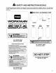
A SAFETY AND INSTRUCTION DECALS The following decals are installed on the generator. If any become damaged or illegible, replace it. The decal part number is listed below and in your parts catalog. Replacement decals can be ordered from your Authorized Toto Distributor.
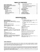
TABLE OF CONTENTS Page SAFETY INSTRUCTIONS -2 SAFETY AND INSTRUCTION DECALS 3 SPECIFICATIONS 4 LOOSE PARTS .. B SET-UP INSTRUCTIONS 612 OPERATION 12 Grounding Generator 12 Q Operation Emergency Shut Down .. Extension Cord Requirements . 14 Moving Vehicle 14 Ground Fault Circuit Interrupter 14 Clog Test Procedure 14 Ground Fault Circuit interrupter Test Record .. 15 Generator Safety Interlock Test 15 Motor Starting LOAD CALCULATION . MAINTENANCE General Maintenance Brit Pensioning TROUBLE SHOOTING .. ..
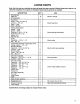
LOOSE PARTS Note: Use this chart as a checklist to assure all parts have been received. Without these parts, total set—up cannot be completed. If any parts are damaged replace before generator is installed. DESCRIPTION Wire Harness Cable Tie Wire Assembly Fuse Block Screw — #10-24 x 3/4” ig. Lockout — #1024 Decal — Fuse Fuse — 20 amp Parking Brake Switch Spacer ~ Long Spacer ~ Short Screw #1024 x Ig. Screw #10-24x 2" Ig.
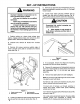
SET-UP INSTRUCTIONS WARNING improper installation of generator can re~ slut in personal injury or death. » Kit must be installed by a qualified technician. ® Each step of installation instructions must be carefully completed. » Inspect installed wire harnesses to assure they are well secured and protected to avoid damage by moving parts of the machine or from rubbing against sharp edges. 1. Position vehicle on a clean, level surface, stop engine, engage parking brake and remove key from ignition switch.
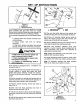
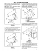
Figure 3 1. Jumper wire 2. Vehicle Wire harness 14. Using generator wire heiress supplied in kit, plug open connector with Grey lead wires into vehicle harness where interlock j Jumper wire was removed. Do not remove jumper wire from remaining connector. 18. lf machine is equipped with an APU Electric Clutch Kit: A, Unplug clutch wire shames connector from vehicle harness. B. Unplug jumper wire from kit harness connector. C.
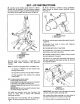
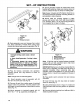
SET-UP INSTRUCTIONS 28, Loosely mount parking brake switch to vehicle console with (2) spacers, #1024 screws, washers and nuts, as shown in figure 6. Different length spacers are used to mount switch level as shown in figure 6. Figure 6 . Parking brake switch . Short spacer . Long spacer . Washer PONTOON. Plug single wire assembly, if applicable, and parking brake switch connector into generator harness. Note: If machine is equipped with a 1/3 Platform Lift A.
SET-UP INSTRUCTIONS Note: On Workman 3100, install Auxiliary Power Unit Kit and mount pulley in place of bearing hub. Refer to kit installation instructions. Note: Bearings must be applied without applying pressures to inner race of bearing. Figure 9 1. Jackstraw pulley 42. Remove nut and washer securing hydraulic pump pulley to jack shaft and remove pulley (Fig. 9). 43, Install new pulley 1o jack shaft with new nut and washer. Pulley to be positioned so small sheave is toward front of machine (Fig. 10).
INSTRUCTIONS Figure 13 1. Generator 2. Cover 3. Ha mess Connector 49. Route generator cover and harness from control box, along underside of vehicle frame, along cross member and above belly guards to generator {Fig 13). A\ warning 84, Secure generator harness to vehicle frame cross member with cable ties. Make sure shames does not come in contact with any hot, sharp or rotating parts.
SET~UP INSTRUCTIONS Figure 15 1. Generator shield 2. Generator baffle 60. Place generator shield and baffle assembly against right hand frame channel, aligning rear holes in baffle with rear fuel tank mounting holes. Using front holes in baffle and frame secure together with (2) x 3/4” Ig. cap screws and flange nuts (Fig. 16). Figure 16 1. Shield & baffle assembly 2. Fuel tank supports 3.
SET—UP INSTRUCTIONS Figure 18 1. Spark Arrest or 71. Adjust engine high ogle to 3600 rpm at maximum setting of hand throttle kit as well as with foot throttle. Follow adjustment instructions located in vehicle operators manual and in throttle installation instructions. IMPORTANT: Engine governor must be correctly adjusted to assure proper operation of the generator. If engine speed drops below approximately 3375 rpm, the speed sensor will turn the generator off.
OPERATING INSTRUCTIONS 4. Secure other end of wire to grounding electrode with clamp or devise as designated by local, state or other codes. Typical Grounding Electrodes e Underground metal water pipes which are in direct contact with the earth for more than 10 feet. & Ground rod or ground pipe with a minimum length of 8 feet. 1. Galvanized pipe or galvanized conduit {(3/4 inch trade size minimum) 2. Solid iron, steal rod or stainless steel rod (5/8 inch minimum diameter) 3.
OPERATING INSTRUCTIONS Emergency Shut Down A. Switch control panel on—off switch to off position. OR B. Switch workman vehicle ignition switch to off position. EXTENSION CORD REQUIREMENTS Use an extension cord suitable for outdoor use and one that complies with the requirements specified in the International Electric Code. Make sure your cord is in good condition; if damaged, replace. Use a cord that is fare enough to carry the current the appliance will draw.
OPERATING INSTRUCTIONS 2. If the GUCCI tests okay, restore power by pushing the RESET bunion back in. Test lamp should again light. THE RESET BUTTON MUST BE PUSHED FIRMLY AND FULLY INTO PLACE UNTIL IT LOCKS AND REMAINS DEPRESSED AFTER PRESSURE HAS BEEN REMOVED, IF THE GUCCI FAILS TO RESET PROPERLY, DO NOT USE CALL A QUALIFIED ELECTRICIAN, 3. IF GUCCI TRIPS 8Y ITSELF, reset and perform test procedures 1. and 2. above.
LOAD CALCULATION The generator has a maximum continuous capacity of 4200 wails when the cooling air going into the generator (16.5° C.). The capacity of the generator decreases 1% for each I0° . (6.5° C.). increase in temperature of the cooling air. The Engine can increase the cooling temperature as much as 30° F. (16.6° C.) depending on ambient temperature. 1.
MAINTENANCE GENERATOR MAINTENANCE The generator requires no normal maintenance other than keeping the rear air inlet cover and the front air outlet, clear of obstructions. Inspect rear cover vents and front outlet openings often. Deflectors are provided to reduce accumulation of mud, dirt, grass, snow, ice and other materials that can block cooling air. Dirt build—up can usually be removed with a garden hose. Loos materials such as grass and leaves can be removed by vacuum.
TROUBLE SHOOTING GUIDE Generator crutch does not engage 1. Parking brake interlock switch 1. Adjust or replace 2. Blown fuse 2. Replace fuse 3. Electric clutch does not engage 3. Test circuit {No power to clutch) 4. Engine governor not set at 3600 4. Adjust governor rpm Generator is running but does not 1. Fatuity Capacitor 1, Replace capacitor generate 2. Circuit breaker open due to short |2. Inspect wiring and repair circuit or overload 3, Shorted or open armature winding | 3. Replace generator 4.