
Operator's Manual


FORM NO. 3326-986
The Toro Company2001 TPS
MODEL NO. 07415
INSTALLATION
INSTRUCTIONS
For Workman 3000 Series
REMOTE HYDRAULIC CONTROL KIT
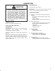
SAFETY AND INSTRUCTION DECALS
The following safety and instruction decals are to be installed on the kit. If any become damaged or illegible,
replace them. Decal part numbers are listed below and in the parts catalog. Order replacements from your
Authorized Toro Distributor.
ON COUPLER BRACKET
(Part No. 92-2610)
ON CENTER CONSOLE COVER
(Part No. 92-2609)
ON REAR AXLE
(Part No. 92-2611)
CAUTION
QUICK COUPLERS UNDER PRESSURE
STOP ENGINE, APPLY PARKING
BRAKE AND PLACE REMOTE VALVE
IN FLOAT DETENT POSITION TO
REMOVE PRESSURE BEFORE
CONNECTING OR DISCONNECTING
QUICK COUPLERS.
INSTALLATION
1. Position vehicle on a clean, level surface, stop
engine, engage parking brake and remove key from
ignition switch.
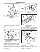
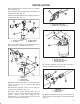
2. Unscrew and remove all knobs from console levers
(Fig. 1).
3. Remove (6) screws securing outside edge of
center console cover plate to frame and remove cover
plate (Fig. 1).
4. Remove (2) capscrews and locknuts securing
front legs of seat frame to sides of vehicle floor (Fig. 1).
5. Remove (2) capscrews and lockwashers securing
seat frame brackets to vehicle frame (Fig. 1). Remove
seat frame from vehicle.
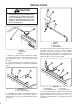
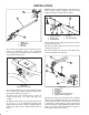
6. Loosen hose clamp securing overflow tube to
radiator and slide tube off radiator opening (Fig. 2).
Plug overflow tube to prevent fluid from escaping.
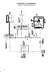
Figure 1
1. Center console cover
2. Seat frame
1
2
3
3. Seat assembly
4. Skirt & fender assembly
4