
Installation Instructions
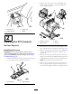
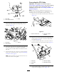
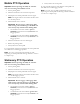


10.Applythewarningdecaltolower-rearcrosstubenext
toexistingdecal,justabovehitchpoint(Figure21).
Figure21
1.Rearcrosstube2.Warningdecal
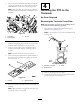
11.Usingthe5cabletiessuppliedinkit,securethePTO
cabletotheexistingwiring.
5
CompletingthePTO
Installation
NoPartsRequired
Procedure
1.Connectthebatterycablestothebatteryandinstall
thebatterycover;referto1PreparingtoInstallthe
Kit(page2).
2.Testtheinterlocksystem,refertoCheckingInterlock
SysteminOperator’sManual.
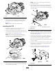
3.Shutengineoffandinspectthemachineforhydraulic
uidleakswherethePTOhousingmountsontothe
transaxle.
Note:Repairalluidleaks.
4.StarttheengineandoperatethePTO.
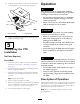
5.Removethecylinderlockfromthebed-liftcylinderand
stowitinthebracketsatthebackoftheROPSpanel;
referto1PreparingtoInstalltheKit(page2).
6.Lowerthebedandshutofftheengine.
Operation
WARNING
ThevehiclemaymoveunexpectedlyifPTOis
engagedandvehicleisshiftedintogear,possibly
resultinginseriousinjurytoabystander.
•DonotshifttransmissionintogearuntilPTO
attachmenthasstoppedrotating,evenifthe
clutchisdepressed.
•MakesurenopersonisaroundthePTOoutput
shaftorthefrontorrearofvehicle.
DANGER
Anuncoveredrotatingsplinecancatchclothing
andresultinseriousinjuryordeath.
•Whenanattachmentisnotconnectedtothe
PTOshaft,disengagedrivetothePTOby
pullingbackonPTOlever.
•ThePTOincludesashield.Thisshieldmust
remaininstalledonthevehicleandingood
condition.
•AlwaysdisengagethePTOandshutoffengine
beforecouplinganyattachmenttothePTO
shaft.
CAUTION
Usingattachmentswithhighinertia(i.e.mowersor
blowers)willincreasetheamountofforcerequired
toshiftthevehicleandwilldamagethetransaxleif
frequentlyshifted.
•Donotshiftvehiclewhilevehicleismovingif
thePTOisengaged.
•Alwaysusetheoptionaloverrunningclutch
whenpoweringahighinertiaattachmentwith
thePTO.
DescriptionofOperation
ThePTOtakespowerfromtheengine,throughthetransaxle,
andsuppliespowerthroughastandard540rpm-splined
shaftattherearofthevehicle.PTOpowercanbeusedfor
bothmobileandstationaryattachments.
Note:RefertoattachmentOperator’sManualforrpm
recommendations.
8