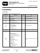
Form No. 3432-281 Rev B Homologation Kit Outcross 9060 Series Traction Unit Model No. 07541 Installation Instructions Installation Loose Parts Use the chart below to verify that all parts have been shipped. Procedure 1 2 Description Use Qty. Wheel chock 2 Prepare the machine. No parts required – Remove the roof panel.
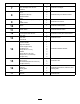
Procedure 7 8 9 10 11 12 13 14 15 16 17 Description Use Qty. Headlight Short headlight wire harness Cable tie Bracket U-nut Bolt (#10 x 1/2 inch) Flasher module Relay Horn-switch assembly (switch and jam nut) Rubber button 2 2 2 1 2 2 1 1 Switch 1 Install the hazard switch Paddle switch 1 Install the flasher switch. Control panel wire harness 1 Install the control panel wire harness.
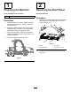
1 2 Preparing the Machine Removing the Roof Panel Parts needed for this procedure: No Parts Required 2 Wheel chock Procedure 1. Procedure 1. Park the machine on a level surface, move the shift lever to the NEUTRAL position, and lower the attachments. 2. Engage the parking brake, shut off the engine, remove the key, and wait for all movement to stop before leaving the operator’s seat. 3.
3 Installing the Rear Lights Parts needed for this procedure: 4 Nut (5/16 inch) 2 Tail light assembly 2 Tail light assembly bracket 4 Hex-head bolt (5/16-18 x 1 inch) Procedure 1. Secure the tail light assemblies to the tail light assembly brackets (Figure 3). Note: Ensure that the yellow lens is on the top of the bracket.
2. Remove the bolts and nuts on the left machine as shown in Box A of Figure 4. Note: Install the light assemblies on one side at a time. g275216 Figure 4 3. Secure the tail light assembly and bracket to each side of the machine using 4 bolts (5/16-18 x 1 inch) and 4 nuts (5/16 inch). Note: Ensure that the turn signal part of the light is on the bottom. 4. Repeat on the right side of the machine. 5.
4 Installing the Front Lights Parts needed for this procedure: 6 Bolt (1/4-20 x 3/4 inch) 6 Locknut (1/4 inch) 2 Front light assembly 1 Right, front light bracket 1 Left, front light bracket 1 Wire harness 1 Push mount fastener Procedure 1. Attach the front light assemblies to the front light brackets (Box A and B of Figure 5). Ensure that the yellow lens is on the outside (Box D of Figure 5). g274362 Figure 5 1. Bolts —1/4-20 x 3/4 inch (6) 2. Nuts —1/4 inch (6) 6 3.
2. Attach the front light assemblies and brackets to both sides of the machine using 6 bolts (1/4-20 x 3/4 inch) and 6 nuts (1/4 inch) as shown in Boxes C and D in Figure 5. 3. Route and connect the wire harness as shown in Figure 6. Note: Secure the excess harness using the push mount fastener and cable tie (Figure 6). 4. Insert the push mount fasteners in the holes on the frame (Figure 6). g275551 Figure 6 1. Machine wire harness 4. Push mount fasteners 2. Kit wire harness 5.
(5/16 inch), and torque the bolt and nut to 1978 to 2542 N∙cm (175 to 225 in-lb). 5 Installing the Horn Parts needed for this procedure: 1 Horn Attaching the Horn to the Machine g254491 Figure 9 1. Bolt (frame/bracket 5/16 x 2-3/4 inches) 3. Flange locknut (5/16 inch) 2. Bracket (horn) 3. g254486 Figure 7 1. Connect the terminal receptacles for the yellow and black wires onto the blade terminals of the horn (Figure 10).
6 Installing the Speed Decal, License Plate Light, and Backup Light Parts needed for this procedure: 1 Bracket 2 U-nut g286110 Figure 12 1 License plate light 1 Speed decal and light plate 2 Rounded-head bolt (#10-24 x 3/4 inch) 4 Carriage bolt (1/4-20 x 1/2 inch) Attach the assembly to the bracket using 1 rubber bumper, 1 washer, and 1 nut (1/4 inch). 3 Nut (1/4 inch) Note: Use pliers to hold the bumper in place.
5. Attach the backup light assembly to the bracket using 2 carriage bolts (1/4–20 x 1/2 inch) and 2 nuts (1/4 inch). 7. Attach the assembly to the machine using 2 bolts (5/16-18 x 3 inches), 2 washers, and 2 nuts (5/16 inch). Note: For Cab machines, remove the existing hinge bolts. g286112 Figure 14 1. Bolt (1/4-20 x 1/2 inch) 6. 2. Nut (1/4 inch) Route the license plate light wire harness. g286113 Figure 16 8.
9. 12. Install the license plate light using 2 bolts (#10-24 x 3/4 inch). Install the backup light. g286116 g286115 Figure 19 Figure 18 10. Route the harness and connect it to the machine wire harness (Figure 20). 11. Secure the harness using the cable ties (Figure 20).
g281172 Figure 20 1. Rear wire harness 2. Cable ties 3.
7 Installing the Headlights Parts needed for this procedure: 2 Headlight 2 Short headlight wire harness 2 Cable tie Procedure 1. Disconnect and remove the machine headlights. 2. Attach the short headlight wire harnesses to the headlights as shown in Figure 21. 3. Install the headlight assemblies onto the machine. g285776 Figure 21 4. Secure the short wire harnesses to the frame using 2 cable ties (Figure 21). 5. Connect the 2 small harnesses to the machine harness. 6.
8 Installing the Relay and Flasher Module Parts needed for this procedure: 1 Bracket 2 U-nut 2 Bolt (#10 x 1/2 inch) 1 Flasher module 1 Relay Installing the Relay and Flasher Module 1. Remove the 3 bolts and rotate the control panel out to the right (Box A of Figure 22). 2. Remove the relay and bolt shown in Box B of Figure 22. g278143 Figure 22 3. Install the bracket and relay using the 2 bolts previously removed (Box B of Figure 23). 4.
g281175 Figure 23 15
Installing the Horn Switch 9 1. Remove the plug from the steering column-panel (Figure 26). Installing the Horn Switch Parts needed for this procedure: 1 Horn-switch assembly (switch and jam nut) 1 Rubber button Removing the Steering-Column Panel 1. Remove the 4 socket-head screws that secure the steering column-panel to the dash (Figure 24). g272241 Figure 26 1. Rubber cap 3. Jam nut 2. Plug (steering column-panel) 4. Switch (horn) 2. Assemble the jam nut onto the horn switch (Figure 26).
g272242 Figure 27 1. Blade connector (switch) 2. 2-socket connector (HORN SWITCH) 10 Installing the Hazard Switch Parts needed for this procedure: 1 Switch Procedure Install the hazard switch as shown in Figure 28.
11 Installing the Flasher Switch Parts needed for this procedure: 1 Paddle switch Procedure Install the paddle switch and connect it to the kit wire harness (Figure 29). Install the steering column panel. g274361 Figure 29 12 Installing the Control Panel Wire Harness Parts needed for this procedure: 1 Control panel wire harness Procedure Secure the control panel wire harness to the controls and connect it to the machine wire harness (Figure 34). Install the control panel cover.
g281161 Figure 30 19
13 Installing the Fuses Parts needed for this procedure: 2 15 A fuse 1 10 A fuse 1 Fuse decal Procedure Install a 15 A fuse into the fuse block slot at column C, row 3. Install a 15 A fuse into the fuse block slot at column D, row 2. Install the 10 A fuse into the fuse block slot at column C, row 4. g281170 Figure 31 1. 15 A fuse (C3) 3. 15 A fuse (D2) 2. 10 A fuse (C4) Install the decal sticker on the fuse block decal at column C, row 3 (Figure 32).
g281169 Figure 32 14 Installing the Extended Fenders Parts needed for this procedure: 2 Fender support 1 Left front fender 1 Right front fender 2 Fender support strap 8 Nut (5/16 inch) 8 Bolt (5/16-18 x 1 inch) 3 Washer 3 Bolt (5/16-18 x 3/4 inch) 2 Bolt (3/4-10 x 3-1/2 inches) 2 Nut (3/4 inch) 21
Procedure 1. Trim the rubber kit fenders if you have a front attachment with loader arms on your machine (Figure 33). g285774 Figure 33 1. 12.1 cm (4 3/4 inches) 2. 2. 26.1 cm (10 1/4 inches) Remove the current fender (Figure 34 and Figure 35). Note: Keep the hardware.
g281162 Figure 34 g275235 Figure 35 3. If your fender does not have pre-drilled holes, follow steps 4 to 7. If your fender does have pre-drilled holes, go to step 8. 4. Line up the old and new fenders, placing the new fender on top (Figure 36). 5. Secure the 2 fenders together using the hardware removed from the machine fender.
6. Mark the holes to be drilled (Figure 36). 7. Drill 3 holes 9.5 mm (0.375 inch) in the old fender (Figure 36). g281163 Figure 36 1. Fender extenders 2. Drill holes, 9.5 mm (0.375 inch) 3. Machine fenders 4.
8. Secure the fenders and support straps using 8 bolts (5/16-16 x 1 inch), 8 washers (3/8 inch), and 8 (5/16 inch) nuts (Figure 37). g281164 Figure 37 1. Bolt (5/16-16 x 1 inch) 3. Support strap 2. Washer (3/8 inch) 4.
9. Attach the fender assemblies to the machine using the hardware removed from the machine fender (Figure 38). g281165 Figure 38 1. Existing bolts 10. Discard the shim removed in step 2. 11. Secure the fender assemblies to the step using the existing bolts and nuts removed from the machine fender and 2 shims included in this kit (Figure 39). g281166 Figure 39 1. Existing bolt 3. Existing nut 2. Shim 12.
g281167 Figure 40 1. Bolt (5/16-16 x 1 inch) 4. Bolt (3/4-10 x 3-1/2 inches) 2. Washer (3/8 inch) 5. Nut (3/4 inch) 3. Nut (5/16 inch) 13. Attach the fender assemblies to the machine frame using 2 bolts (3/4-10 x 3-1/2 inches) and 2 nuts (3/4 inch) as shown in Figure 40.
15 Installing the Visor Parts needed for this procedure: 1 Visor 1 Visor mount 3 Flat head bolts (#10-24 x 3/4 inch) 3 Nut (#10-24 inch) Procedure 1. Remove the 2 bolts on the left side of the top control panel (Figure 41). 2. Install the visor mount using the 2 bolts previously removed (Figure 41). 3. Install the visor on the visor mount using 3 bolts (#10-24 x 3/4 inch) and 3 nuts (#10-24 inch) as shown in Figure 41.
16 Installing the Speed Decal, Reflectors, and Identity Plate Parts needed for this procedure: 2 Speed decal 2 Reflector 1 Identity plate 4 Rivet Procedure 1. Install the speed decals on both sides of the machine (Figure 42). g281173 Figure 42 1. Speed decal 2. Serial plate 2. Stamp the serial number onto the fender, using 7 mm text size or larger, in the location shown in Figure 43. 3.
• Front axle weight • Rear axel weight 4. Mark and drill 4 (size 9) 5 mm (0.196 inch) holes for the serial plate. 5. Install the serial plate with 4 rivets on the front right bumper of the machine (Figure 43). g281174 Figure 43 1. 25.4 cm (10 inches) 3. 3.8 cm (1-1/2 inch) 2. Serial plate and rivets 4. Serial number stamp location 6. Install the 2 reflectors as shown in Figure 46.
g275269 Figure 44 31
Operation 17 Controls Installing the Trim Switches Parts needed for this procedure: 12 Hinge trim 2 Bed trim Procedure Install the trim, on both sides, of the machine as shown in Figure 45. g264488 Figure 46 1. Turn signal switch 3. Hazard switch 2. Horn button Turn-Signal Switch Press down on the left side of the turn-signal switch (Figure 46) to activate the left-turn signal. The center position is off.