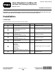
Form No. 3450-711 Rev B Glass Windshield and Wiper Kit Workman® UTX Passenger Utility Vehicle Model No. 08112 Installation Instructions Important: If you are installing this kit and the Overhead Console Kit (Model 08130) at the same time, install the Glass Windshield and Wiper Kit first, then the Overhead Console Kit. Installation Loose Parts Use the chart below to verify that all parts have been shipped. Procedure 1 Description Use Qty.
1 Preparing the Machine No Parts Required Procedure 1. Park the machine on a level surface. 2. Shift the transmission lever to the P (Park) position. 3. Shut off the engine and remove the key. 2 Installing the Latch-Mount Bracket and Latch Parts needed for this procedure: 1 Latch-mount bracket 4 Torx-head screw (M6 x 25 mm) 2 Washer (6 mm) 1 Latch Procedure 1. Remove the 2 plastic rivets from the dash (Figure 1).
2. Using the latch-mount bracket as the template, mark and then drill 2 holes (5/16 inch) into the dash (Figure 2). g382255 Figure 2 3. Secure the latch-mount bracket to the dash using 2 torx-head screws (M6 x 25 mm) and 2 washers (6 mm) as shown in Figure 3. 4. Torque the 2 torx-head screws (M6 x 25 mm) to 3.6 to 4.5 N∙m (32 to 40 in-lb).
5. Loosely secure the latch to the dash using 2 torx-head screws (M6 x 25 mm) as shown in Figure 4. Do not torque the bolts until later.
3 Installing the Windshield Parts needed for this procedure: 1 Windshield 2 Nut plate (8 mm) 4 Button-head bolt (M8 x 20 mm) Procedure Important: You need 2 people for installing the windshield. 1. Align the windshield with the opening on the machine. 2. Loosely secure the windshield using 2 nut plates (8 mm) and 4 button-head bolts (M8 x 20 mm) as shown in Figure 5. Ensure that the windshield is even on each side of the ROPS when installing the fasteners. g382258 Figure 5 3.
4 Installing the Gas Springs Parts needed for this procedure: 2 Gas spring 4 Strut mount 4 Button-head bolt (M6 x 10 mm) Procedure 1. Secure a strut mount to the right windshield frame using a button-head bolt (M6 x 10 mm) as shown in Figure 6. Note: It is recommended to use the middle hole on the windshield frame. 2. Secure a strut mount to the right door-latch bracket using a button-head bolt (M6 x 10 mm) as shown in Figure 6. 3. Repeat steps 1 and 2 on the other side. 4.
5. Secure the 2 gas springs to the strut mounts (Figure 7). Ensure that you orient the gas spring as shown in Figure 7. g382260 Figure 7 5 Tightening the Latch No Parts Required Procedure 1. If needed, adjust the latch, and ensure that windshield latches correctly. 2. Torque the 2 torx-head screws (M6 x 25 mm) to 11 N∙m (96 in-lb).
6 Installing the Wiper Motor, Arm, and Blade Parts needed for this procedure: 1 Wiper motor 1 Wiper arm 1 Wiper blade 1 Bulkhead fitting 1 Wiper hose 1 Washer bottle 2 Hex-washer head bolt (1/4 x 5/8 inch) 8
Procedure 1. Secure the wiper motor to the front ROPS crosslink using the fasteners provided with the motor (Figure 8). Box A represents the fasteners needed to secure the wiper motor housing. Box B represents the fasteners needed to secure the wiper motor and wiper arm. The crosslink is shown as a solid, black line in box A and B of Figure 8.
2. Secure the bulkhead fitting to the front ROPS crosslink using the washer and nut included with the fitting (Figure 9). Hand-tighten the nut.
3. While holding the end of the wiper arm with a rag, secure the wiper arm to the motor using the nut and lock washer from the motor assembly (Figure 10). g388860 Figure 10 4. Secure the wiper blade to the hook on the wiper arm (Figure 11).
5. Attach the hose line on the wiper arm to the bulkhead fitting (Figure 12). g389334 Figure 12 6. Install the wire raceway channel and route the wiper hose through the raceway channel; refer to procedure Installing the Wire Raceway Channel in the Overhead Console Kit (Model 08130) Installation Instructions. 7. Attach the wiper hose to the bulkhead fitting (Figure 13).
8. Secure the washer bottle to the front frame column mount using the 2 hex-washer head bolts (1/4 x 5/8 inch) as shown in Figure 14. 9. Attach the wiper hose to the washer bottle (Figure 14).
10. Connect the machine wire-harness connector labeled WASHER PUMP to the washer bottle. You will find the harness connector underneath the front frame shock tower (Figure 15). g383292 Figure 15 11. Fill the washer bottle with the appropriate climate-compatible windshield washer fluid.
7 Installing the Switch Parts needed for this procedure: 1 Switch Procedure 1. Install the switch into the opening of the console switch bracket (Figure 16) from the Overhead Console Kit (Model 08130). g382341 Figure 16 2. Secure the console switch bracket and the remaining 3 plugs; refer to the Overhead Console Kit (Model 08130) Installation Instructions. 3.
Operation Operating the Wiper Switch Down position—Wiper off Middle position—Continuously run the wiper Up position—Momentarily spray washer fluid on-demand 16