Form No. 3364-385 Rev B Front Lift Frame Sand/Infield Pro® 5040 Traction Unit Model No. 08712—Serial No. 310000001 and Up Operator's Manual This product complies with all relevant European directives, for details please see the separate product specific Declaration of Conformity (DOC) sheet. Note: Determine the left and right sides of the machine from the normal operating position. Setup Loose Parts Use the chart below to verify that all parts have been shipped.
Procedure 5 6 7 8 Description Qty.
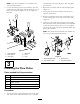
1 2 Installing the Lift Valve Parts needed for this procedure: G003661 Figure 2 1. Right hand wheel shroud 5. Disconnect and remove the center shroud from the frame (Figure 3). 2 Straight hydraulic fitting with O-ring 2 90 degree Hydraulic fitting with O-ring 1 Lift valve 1 Valve plate 3 Bolt, 1/4 x 3 inches 3 Locknut, 1/4 inch 2 Bolts, #10 x 1-1/4 inches 2 Locknuts 1 Lift lever Procedure 1.
Note: The valve installation is very similar to the vale currently installed. 3. Loosely mount the pivot lever assembly to the valve spool and to the offset link with 2 bolts (#10 x 1-1/4 inch) and 2 locknuts (Figure 5). Do not tighten at this time. 5 and locknuts as shown in Figure 6. Do not tighten the fasteners. 2. Repeat the procedure with the left hand plow plate (Figure 6). 3. Jack up the front of the machine until the front wheel is off the floor. 4.
4. Insert the push arm tubes onto the right and left plow plates aligning the cylinder pin guides with the holes in the plow plates (Figure 8). 4 Note: If unable to get the push arm tubes around the plow plates, loosen the nuts securing the plow plates to the castor fork. Installing the Push Arms and Hitch Frame 5. Mount each cylinder pin to each plow plate with a bolt (5/8 x 1-1/2 inches) and a washer (1.68 O.D. x .65 I.D.) as shown in Figure 8. Torque the bolts to 150 ft-lb.
5 Installing the Hydraulic Cylinder Parts needed for this procedure: 3 4 g018303 1 45 degree Hydraulic fitting with O-ring 1 Hydraulic cylinder 1 90 degree Hydraulic fitting with O-ring 1 Small retaining ring 1 Pin 2 Large retaining ring Procedure Figure 9 1. 1. Hitch frame bracket 3. Hose guide 2. Hitch frame 4. Hitch frame tube 8. Secure the frame adapter to the hitch frame with a tube, clevis pin and cotter pin (Figure 10).
ring (Figure 12). The cylinder hydraulic ports are to be positioned forward. 4. Mount the cylinder rod to the push arm straps with a pin and 2 retaining rings (Figure 12). or cap the fitting on the cooler using one of the protective shipping caps removed from the tube assembly, part no. 108–8447 (Figure 14). 2 1 G003671 Figure 13 1. Oil cooler g018313 3. Secure the remaining hydraulic tube to the frame with the clamp and fasteners previously removed Figure 12 1. Hydraulic cylinder 4.
1 2 3 4 5 6 7 G003672 Figure 14 1. New valve 3. Existing valve 5. Wire hose holder 2. Tube assembly, part no. 108-8447 4. Hydraulic hose, part no. 108-8449 6. Hydraulic hose, part no. 108-8453 7. Hydraulic hose, part no. 108-8454 Figure 15 1. Cable tie 2. Hydraulic hose, part no. 108-8449 3. Hydraulic hose, part no. 108-8453 8 4. Hydraulic hose, part no.
Figure 16 1. Cable tie 3. Hydraulic hose, part no. 108-8453 2. Hydraulic hose, part no. 108-8449 4. Hydraulic hose, part no.
WARNING 7 Hydraulic fluid escaping under pressure can penetrate skin and cause injury. • If hydraulic fluid is injected into the skin it must be surgically removed within a few hours by a doctor familiar with this type of injury. Gangrene may result if this is not done. • Keep body and hands away from pin hole leaks or nozzles that eject high pressure hydraulic fluid. • Use cardboard or paper to find hydraulic leaks.
Operation 10. Secure the control panel in place with the fasteners previously removed (Figure 18). Specifications 1 2 Net Weight 85 lbs. (38.5 kgm) Attachments/Accessories A selection of Toro approved attachments and accessories are available for use with the machine to enhance and expand its capabilities. Contact your Authorized Service Dealer or Distributor or go to www.Toro.com for a list of all approved attachments and accessories. G003676 Figure 18 1. Knob Operating Tips 2. Control panel 12.
Maintenance Greasing the Lift Frame The front lift frame has 5 grease fittings (Figure 19) that must be lubricated regularly with No. 2 General Purpose Lithium Base Grease. If machine is operated under normal conditions, lubricate all bearings and bushings after every 100 hours of operation. Lubricate the bearings and bushings immediately after every washing, regardless of the interval listed.
Schematics G003678 Hydraulic Schematic (Rev.
Notes: 14
Notes: 15
The Toro Total Coverage Guarantee A Limited Warranty Conditions and Products Covered The Toro Company and its affiliate, Toro Warranty Company, pursuant to an agreement between them, jointly warrant your Toro Commercial product (“Product”) to be free from defects in materials or workmanship for two years or 1500 operational hours*, whichever occurs first. This warranty is applicable to all products with the exception of Aerators (refer to separate warranty statements for these products).