Form No. 3354-251 Rev C Front Lift Frame Sand/Infield Pro® 5040 Traction Unit Model No. 08712—Serial No. 260000001 and Up Installation Instructions Note: Determine the left and right sides of the machine from the normal operating position. Loose Parts Use the chart below to verify that all parts have been shipped. Procedure 1 2 3 4 5 © 2007—The Toro® Company 8111 Lyndale Avenue South Bloomington, MN 55420 Description Qty.
Procedure 6 7 8 Description Qty. Tube assembly Hydraulic hose Hydraulic hose Hydraulic hose Wire hose holder Thread forming screw, 5/16 x 3/4 inches Plastic cable tie Lever guide plate Flange head screw Washer Control panel decal Control panel Knob Plastic cable tie Installation Instructions Parts Catalog 1 1 1 1 1 2 3 1 2 2 1 1 1 3 1 1 2 Use Install the hydraulic hoses. Installing the control panel and lever guide plate. Read the documentation and store it in a safe location.
1 1 Removing the Shrouds No Parts Required G003661 Figure 2 Procedure 1. Right hand wheel shroud 1. Jack up the rear of the machine and position blocks under the rear wheel motor mounts. Remove the right rear tire. 5. Disconnect and remove the center shroud from the frame (Figure 3). 2. Remove the 4 washers and bolts mounting the control panel to the console (Figure 1). Unplug the wire from the hour meter. Remove the control panel (Fig. 1). 3.
Note: The valve installation is very similar to the vale currently installed. 2 3. Loosely mount the pivot lever assembly to the valve spool and to the offset link with 2 bolts (#10 x 1-1/4 inch) and 2 locknuts (Figure 5). Do not tighten at this time.
and locknuts as shown in Figure 6. Do not tighten the fasteners. 4 2. Repeat the procedure with the left hand plow plate (Figure 6). Installing the Push Arms and Hitch Frame 3. Jack up the front of the machine until the front wheel is off the floor. 4. Remove and discard the 2 bolts securing the front of the steering pivot to the top of the castor fork (Figure 6). Parts needed for this procedure: 5.
4. Insert the push arm tubes onto the right and left plow plates aligning the cylinder pin guides with the holes in the plow plates (Figure 8). 1 2 Note: If unable to get the push arm tubes around the plow plates, loosen the nuts securing the plow plates to the castor fork. 5. Mount each cylinder pin to each plow plate with a bolt (5/8 x 1-1/2 inches) and a washer (1.68 O.D. x .65 I.D.) as shown in Figure 8. Torque the bolts to 150 ft-lb. 3 G003667 Figure 9 1. Hitch frame bracket 2. Hitch frame 1 3.
ring (Figure 12). The cylinder hydraulic ports are to be positioned forward. 4. Mount the cylinder rod to the push arm straps with a pin and 2 retaining rings (Figure 12). 5 Installing the Hydraulic Cylinder 2 1 3 Parts needed for this procedure: 1 45 degree Hydraulic fitting with O-ring 1 Hydraulic cylinder 1 90 degree Hydraulic fitting with O-ring 1 Small retaining ring 1 Pin 2 Large retaining ring G003670 Procedure 1.
or cap the fitting on the cooler using one of the protective shipping caps removed from the tube assembly, part no. 108–8447 (Figure 14). right side of the valve and the straight end of the hose to the vacant oil cooler fitting (Figure 14). Refer to Figure 15 and Figure 16 for hose routing. 6. Mount the wire hose holder to the left frame tube with 2 thread forming screws (5/16 x 3/4 inch) (Figure 14). 7. Connect the short 90 degree fitting end of hydraulic hose, part no.
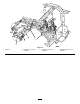
Figure 15 1. Cable tie 2. Hydraulic hose, part no. 108-8449 3. Hydraulic hose, part no. 108-8453 9 4. Hydraulic hose, part no.
Figure 16 1. Cable tie 2. Hydraulic hose, part no. 108-8449 3. Hydraulic hose, part no. 108-8453 4. Hydraulic hose, part no.
7 Hydraulic fluid escaping under pressure can penetrate skin and cause injury. Installing the Control Panel and Lever Guide Plate • If hydraulic fluid is injected into the skin it must be surgically removed within a few hours by a doctor familiar with this type of injury. Gangrene may result if this is not done.
8. Remove the hour meter from the old control panel and install in the new control panel. Operation 9. Install the new control panel and plug the wire into the hour meter. • The front lift frame is designed to only accept certain attachments. Do not try to install a rear mount attachment to the front lift frame as damage to the machine may occur. 10. Secure the control panel in place with the fasteners previously removed (Figure 18). • To lower the front lift frame, push the lift lever forward.
Maintenance Greasing the Lift Frame The front lift frame has 5 grease fittings (Figure 19) that must be lubricated regularly with No. 2 General Purpose Lithium Base Grease. If machine is operated under normal conditions, lubricate all bearings and bushings after every 100 hours of operation. Lubricate the bearings and bushings immediately after every washing, regardless of the interval listed.
Schematics G003678 Hydraulic Schematic (Rev.
The Toro General Commercial Products Warranty A Two-Year Limited Warranty Conditions and Products Covered The Toro Company and its affiliate, Toro Warranty Company, pursuant to an agreement between them, jointly warrant your Toro Commercial Product (“Product”) to be free from defects in materials or workmanship for two years or 1500 operational hours*, whichever occurs first.