
Installation Instructions


orcapthettingonthecoolerusingoneofthe
protectiveshippingcapsremovedfromthetube
assembly,partno.108–8447(Figure14).
G003671
2
1
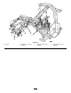
Figure13
1.Oilcooler
2.Hydraulictube
3.Securetheremaininghydraulictubetotheframe
withtheclampandfastenerspreviouslyremoved
4.Connectthetubeassembly,partno.108-8447,to
the90degreettingontheleftsideofthenew
valveandthevacatedttingontheexistingliftvalve
(Figure14).
5.Connectthe45degreettingendofhydraulichose,
partno.108-8449,tothe90degreettingonthe
rightsideofthevalveandthestraightendofthe
hosetothevacantoilcoolertting(Figure14).Refer
toFigure15andFigure16forhoserouting.
6.Mountthewirehoseholdertotheleftframetube
with2threadformingscrews(5/16x3/4inch)
(Figure14).
7.Connecttheshort90degreettingendofhydraulic
hose,partno.108-8453,tothetopstraightttingon
therearofthevalve.Routethehosethroughthe
wirehoseholderandconnectthestraightendofthe
hosetothetophydrauliccylindertting(Figure14).
RefertoFigure15andFigure16forhoserouting.
8.Connectthelong90degreettingendofhydraulic
hose,partno.108-8454,tothebottomstraighttting
ontherearofthevalve.Routethehosethrough
thewirehoseholderandconnectthestraightend
ofthehosetothebottomhydrauliccylindertting
(Figure14).RefertoFigure15andFigure16for
hoserouting.Makesurehosesareroutedawayfrom
anysharp,hotormovingcomponents.
9.Tightenallfastenersandttings.
10.Usingcableties,securethehosestothemachine,at
thelocationsshowninFigure15andFigure16.
12345
G003672
12345
6
7
Figure14
1.Newvalve3.Existingvalve5.Wirehoseholder7.Hydraulichose,partno.
108-8454
2.Tubeassembly,partno.
108-8447
4.Hydraulichose,partno.
108-8449
6.Hydraulichose,partno.
108-8453
8