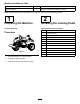
Form No. 3447-659 Rev A Manual Blade Sand Pro®/Infield Pro® 3040 and 5040 Traction Unit Model No. 08714—Serial No. 409600000 and Up Register at www.Toro.com.
serious injury or death if you do not follow the recommended precautions. Introduction g000502 Figure 2 Safety-alert symbol Important: To maximize the safety, performance, and proper operation of this machine, carefully read and fully understand the contents of this Operator’s Manual. Failing to follow these operating instructions or to receive proper training may result in injury. For more information on safe operating practices, including safety tips and training materials, go to www.Toro.com.
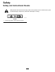
Safety Safety and Instructional Decals Safety decals and instructions are easily visible to the operator and are located near any area of potential danger. Replace any decal that is damaged or missing. decal93-9879 93-9879 1. Stored energy hazard—read the Operator's Manual.
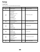
Setup Loose Parts Use the chart below to verify that all parts have been shipped. Procedure 1 2 3 4 5 6 7 Description Use Qty.
Media and Additional Parts Description Use Qty. 1 Operator’s Manual Read the manual before installing the blade. Note: Determine the left and right sides of the machine from the normal operating position. 1 2 Preparing the Machine Installing the Locking Pedal No Parts Required Parts needed for this procedure: Procedure g210130 Figure 3 1. Park the machine on a level surface. 2. Engage the parking brake. 3. Shut off the engine and remove the key.
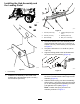
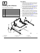
Installing the Hub Assembly and the Locking Pedal g210450 g252122 Figure 5 1. Locknut (5/16 inch).) 4. Carriage bolt (5/16 x 3/4 inch) 2. Locknut (1/4 inch) 5. Washer (9/32 inch) 3. Hub assembly 6. Bolt (1/4 x 2-3/4 inch) 2. Secure the bottom of the hub assembly to the machine frame with a bolt (1/4 x 2-3/4 inch), a washer (1/4 inch), and a locknut (1/4 inch); refer to Figure 5. 3. Torque the locknuts to 71 to 92 N∙cm (100 to 130 in-lb) 4.
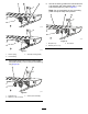
8. Secure the locking pedal to the footrest and the hub assembly with a flat washer (5/8 x 1 inch) and locknut (5/8 inch); refer to Figure 9. Note: Do not overtighten the nut; the locking pedal must pivot freely when pressed. g361296 g252126 Figure 9 1. Nut (5/8 inch) 2. Washer (5/8 x 1 inch) g361297 Figure 7 1. Torsion spring 3. Small pin (locking pedal) 2. Hub assembly 7. Secure the torsion spring to the bushing plate with a flat washer (1-1/8 x 2 inch) and a retaining ring (Figure 8).
Procedure 3 Note: Make sure that the front and rear tires are inflated to 28 to 41 kPa (4 to 6 psi). Installing the Mounting Brackets 1. Parts needed for this procedure: 2. 2 Mounting bracket assembly 4 Bolt (1/2 x 3-1/2 inches) 4 Locknut (1/2 inch) Block up the rear of the machine and remove the rear tires. Note: Position the blocks under the rear wheel motor mounts.
Procedure 4 1. 1 Right lift arm Position the lift arms so that the mounting hole of each lift arm bracket aligns with the holes in the mounting brackets (Figure 11). Secure the right lift arm to the mounting bracket with a clevis pin and hairpin cotter (Figure 11). Loosely install one end of the torsion tube to the right lift arm with 2 bolts (3/8 x 1 inch) and locknuts (3/8 inch); refer to Figure 11. 1 Left lift arm Note: Do not tighten the fasteners at this time.
Procedure 5 Note: Optionally, you can purchase a 60-inch blade. Install it as directed for the 40-inch blade in this section. Installing the Blade 1. Parts needed for this procedure: 1 40-inch blade (optionally, you can purchase and install the 60-inch blade) 2 Brace plate 2 Bolt (3/8 x 1 inch) 6 Locknut (3/8 inch) 4 Bolt (3/8 x 3 inches) Loosely secure a brace plate to each of the inner mounting tabs on the blade assembly. Note: Position the brace plates as shown in Figure 12. 2.
g025725 Figure 12 1. Lift arms 4. Inner mounting tab (2) 2. Brace plate 5. Blade mounting bracket 3.
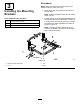
6 Installing the Lift-Arm Foot Pedal Parts needed for this procedure: 1 Lift-arm foot pedal g362720 Figure 14 2 Bolt (3/8 x 3 inches) 4 Locknut (3/8 inch) 2 Spring bracket 1. Hitch tube/vertical frame tube 2. Spring bracket 2 Bolt (3/8 x 2-3/4 inches) 3. Spring rod 2 Extension spring 2 Spring rod Procedure 1. Mount the lift-arm foot pedal to the outside of the left lift arm with 2 bolts (3/8 x 3 inch) and 2 locknuts (3/8 inch). 5. Lift arm 4.
Operation 7 Operating the Blade Adjusting the Spring Tension Pull back on the handle to raise and lock the blade into the transport position. Press the locking pedal to release the blade into the operating position. You can use the blade to push or pull sand and dirt. With the blade in the operating position, simply push forward or pull back slightly on the handle or press on the lift arm foot pedal to control the plowing action.
Declaration of Incorporation The Toro Company, 8111 Lyndale Ave. South, Bloomington, MN, USA declares that the following unit(s) conform(s) to the directives listed, when installed in accordance with the accompanying instructions onto certain Toro models as indicated on the relevant Declarations of Conformity. Model No. 08714 Serial No.
European Privacy Notice The Information Toro Collects Toro Warranty Company (Toro) respects your privacy. In order to process your warranty claim and contact you in the event of a product recall, we ask you to share certain personal information with us, either directly or through your local Toro company or dealer. The Toro warranty system is hosted on servers located within the United States where privacy law may not provide the same protection as applies in your country.
The Toro Warranty Two-Year or 1,500 Hours Limited Warranty Parts Conditions and Products Covered The Toro Company warrants your Toro Commercial product (“Product”) to be free from defects in materials or workmanship for 2 years or 1,500 operational hours*, whichever occurs first. This warranty is applicable to all products with the exception of Aerators (refer to separate warranty statements for these products).