Form No. 3390-732 Rev A Manual Blade Sand Pro®/Infield Pro® 3040 and 5040 Traction Unit Model No. 08714—Serial No. 260000001 and Up Register at www.Toro.com.
Contents WARNING CALIFORNIA Proposition 65 Warning This product contains a chemical or chemicals known to the State of California to cause cancer, birth defects, or reproductive harm. Safety ........................................................................... 3 Safety and Instructional Decals ................................. 3 Setup ............................................................................ 4 1 Installing the Mounting Brackets .............................
Safety Safety and Instructional Decals Safety decals and instructions are easily visible to the operator and are located near any area of potential danger. Replace any decal that is damaged or lost. 93-9879 1. Stored energy hazard—read the Operator's Manual.
Setup Loose Parts Use the chart below to verify that all parts have been shipped. Procedure 1 2 3 4 5 6 Description Qty. Mounting bracket assembly Bolt (1/2 x 3-1/2 inches) Locknut (1/2 inch) Locking pedal Bushing plate Carriage bolt (5/16 x 3/4 inch) Locknut (5/16 inch) Torsion spring Flat washer (1.
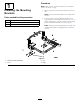
Procedure 1 Note: Make sure that the front and rear tires are inflated to 28 to 41 kPa (4 to 6 psi). 1. Block up the rear of the machine and remove the rear tires. Installing the Mounting Brackets Note: Position the blocks under the rear wheel motor mounts. Parts needed for this procedure: 2 Mounting bracket assembly 4 Bolt (1/2 x 3-1/2 inches) 4 Locknut (1/2 inch) 2.
Procedure 2 1. Install the bushing plate to the inside of the left foot rest with 2 carriage bolts (5/16 x 3/4 inch) and locknuts (5/16 inch) as shown in Figure 3. Installing the Locking Pedal 2. Insert the large stud of the locking pedal through the hole in the left foot rest and through the bushing plate (Figure 3). Parts needed for this procedure: 3. Slide the torsion spring onto the bushing plate while hooking the spring ends onto the floor plate and the small locking pedal stud (Figure 3).
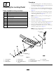
Procedure 3 1. Position the lift arms so that the mounting hole of each lift arm bracket aligns with the holes in the mounting brackets (Figure 4). Installing the Lift Arms 2. Secure the right lift arm to the mounting bracket with a clevis pin and hairpin cotter pin (Figure 4). Parts needed for this procedure: 1 Right lift arm 1 Left lift arm 2 Clevis pin 2 Hairpin cotter pin 1 Torsion tube 4 Bolt (3/8 x 1 inch) 4 Locknut (3/8 inch) 3.
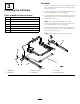
Procedure 4 Note: Optionally, you can purchase a 60 inch blade. Install it as directed for the 40 inch blade in this section. 1. Loosely secure a brace plate to each of the inner mounting tabs on the blade assembly. Installing the Blade Note: Position the brace plates as shown in Figure 5. Parts needed for this procedure: 1 40-inch blade (optionally, you can purchase and install the 60-inch blade) 2 Brace plate 2 Bolt (3/8 x 1 inch) 6 Locknut (3/8 inch) 4 Bolt (3/8 x 3 inches) 2.
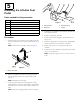
5 Installing the Lift-Arm Foot Pedal Parts needed for this procedure: 1 Lift-arm foot pedal 2 Bolt (3/8 x 3 inches) 4 Locknut (3/8 inch) 2 Spring bracket 2 Bolt (3/8 x 2-3/4 inches) 2 Extension spring 2 Spring rod Figure 7 1. Spring bracket 3. Extension spring 2. Spring rod 4. Lift arm 4. Pull back on the handle to raise and lock the blade into the transport position. 5. Tighten all remaining fasteners. Procedure 6. Connect the extension spring to the lift arm and to a spring rod. 1.
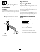
Operation 6 Operating the Blade Adjusting the Spring Tension Pull back on the handle to raise and lock the blade into the transport position. Press the locking pedal to release the blade into the operating position. No Parts Required You can use the blade to push or pull sand and dirt. With the blade in the operating position, simply push forward or pull back slightly on the handle or press on the lift arm foot pedal to control the plowing action.
Declaration of Incorporation The Toro Company, 8111 Lyndale Ave. South, Bloomington, MN, USA declares that the following unit(s) conform(s) to the directives listed, when installed in accordance with the accompanying instructions onto certain Toro models as indicated on the relevant Declarations of Conformity. Model No. 08714 Serial No.
Toro General Commercial Product Warranty A Two-Year Limited Warranty Conditions and Products Covered The Toro Company and its affiliate, Toro Warranty Company, pursuant to an agreement between them, jointly warrant your Toro Commercial product (“Product”) to be free from defects in materials or workmanship for two years or 1500 operational hours*, whichever occurs first. This warranty is applicable to all products with the exception of Aerators (refer to separate warranty statements for these products).