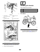
Form No. 3420-125 Rev A Profile Blade Toolbar Sand Pro®/Infield Pro® 3040 and 5040 Traction Unit Model No. 08736—Serial No. 400000000 and Up Register at www.Toro.com.
WARNING CALIFORNIA Proposition 65 Warning This product contains a chemical or chemicals known to the State of California to cause cancer, birth defects, or reproductive harm. Use of this product may cause exposure to chemicals known to the State of California to cause cancer, birth defects, or other reproductive harm. Introduction Read this information carefully to learn how to operate and maintain your product properly and to avoid injury and product damage.
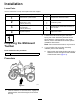
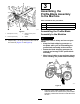
Installation Loose Parts Use the chart below to verify that all parts have been shipped. Procedure 1 2 3 4 Description Qty. Guard mount—pivot bracket 2 Guard Bolt (5/16 x 1 inch) Locknut (5/16 inch) Bolt (5/16 x 1 inch) Eccentric bolt Locknut (5/16 inch) 2 4 4 1 1 2 No parts required – 2. 1 Preparing the Midmount Toolbar 3. Install the guards. Assemble the profile-blade assembly to the machine. Adjust the toolbar.
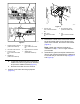
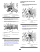
g235478 Figure 4 1. Locknut (3/8 inch—midmount-toolbar kit) 3. Pivot bracket—plain (midmount-toolbar kit) 2. Bolt (3/8 x 3—midmount-toolbar kit) 4. Lift tube—midmount-toolbar kit 5. g235475 Figure 3 1. Toolbar bracket—lift tube (midmount-toolbar kit) 5. Bolt (5/16 x 1 inch—midmount-toolbar kit) 2. Left side of the machine 6. Right side of the machine 3. Locknut (5/16 inch—midmount-toolbar kit) 7. Saddle–right (midmount-toolbar kit) Note: Retain the bolts and locknuts for installation in step 6.
2 Installing the Guards Parts needed for this procedure: 2 Guard 4 Bolt (5/16 x 1 inch) 4 Locknut (5/16 inch) Procedure g235474 Figure 5 1. Locknut (3/8 inch—midmount-toolbar kit) 3. Guard mount—pivot bracket 2. Bolt (3/8 x 3—midmount-toolbar kit) 4. Lift tube—midmount-toolbar kit g235554 Figure 7 1. g235479 Figure 6 1. Left side of the machine 2. Right side of the machine 7. Repeat steps 4 through 6 for the guard mount pivot bracket at the other side of the machine. 8.
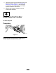
3 Assembling the Profile-Blade Assembly to the Machine Parts needed for this procedure: 1 Bolt (5/16 x 1 inch) 1 Eccentric bolt 2 Locknut (5/16 inch) g235473 Figure 8 1. Bolt (5/16 x 1 inch) 2. Locknut (5/16 inch) 2. Assembling the Profile-Blade Assembly to the Machine 3. Guard mount—pivot bracket 4. Guard DANGER The profile blade is sharp and can cut your hands. • Keep the blade shipping protector on the blade while you are assembling the profile-blade assembly to the machine.
Connecting the Lift Link and Bracket 1. Rotate the profile-blade assembly to align the holes on the lift bracket with the holes in the pivot link (Figure 12). g235550 Figure 10 1. Tool-bar bracket—lift tube 2. Tool-bar tube (profile-blade assembly) 2. 3. 3. Back of the machine 4. Lift bracket (profile blade assembly) Lift the profile blade assembly into tool-bar bracket and support the blade assembly with lifting equipment (Figure 10).
4. Tighten the locknut for the extension spring rod that you loosen in step 2 in 1 Preparing the Midmount Toolbar (page 3), until the spring is tensioned; refer to the Midmount-Toolbar System Installation Instructions. 5. Remove the shipping protector from the profile-blade assembly. 4 Adjusting the Toolbar No Parts Required Procedure g235472 Figure 14 Adjust the toolbar as described in the Mid-Mount Toolbar System Installation Instructions.