
Operator's Manual


g273325
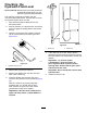
Figure43
1.Cap
3.Hydraulicreservoir
2.Pump
4.Wastehydraulic-uid
container—30L(8US
Gallon)orgreater
2.Pumpthehydraulicuidfromhydraulicreservoir
(Figure43).
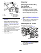
3.Fillthehydraulicreservoirwiththespecied
hydraulicuiduntilthelevelisuptothe
necked-downareaofthedipstick;referto
CheckingtheHydraulic-FluidLevel(page32).
Important:Donotoverllthetankwith
hydraulicuid.
4.Startandruntheengine.Operatetheliftcylinder
untilitextendsandretractsandforwardand
reversewheelmotionisachieved.
5.Shutofftheengineandcheckthehydraulic-uid
levelinthereservoir;adduidifnecessary.
6.Checkforleaks.
Repairanyhydraulicleaks.
7.Installthecentershroud.
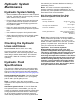
Cleaning
CleaningandInspecting
theMachine
ServiceInterval:Aftereachuse
1.Thoroughlywashthemachinewithagarden
hose—withoutanozzle—sothatexcessive
waterpressuredoesnotcausecontamination
anddamagetothesealsandbearings.
Makesurethatthecoolingnsandthearea
aroundthecooling-airintakearekeptfreeof
debris.
Important:Cleaningtheoilcoolerwith
waterpromotesprematurecorrosionand
damagetocomponents,andcompacts
debris;refertoCleaningtheOilCooler(page
34).
2.Inspectthemachineforpossiblehydraulic-uid
leaks,damage,orweartohydraulicand
mechanicalcomponents.
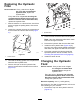
CleaningtheOilCooler
ServiceInterval:Every500hours
1.Removethelowershield(Figure44).
g339970
Figure44
1.Shield2.Oilcooler
2.Usingawand,blowcompressedairinbetween
thefanblades(Figure44)toforcematerialout
fromthedirectionthatitentered.
3.Installtheshield.
34