Form No. 3416-819 Rev A Tooth Rake Sand Pro®/Infield Pro® 3040 and 5040 Traction Unit Model No. 08751—Serial No. 312000716 and Up Register at www.Toro.com.
WARNING CALIFORNIA Proposition 65 Warning This product contains a chemical or chemicals known to the State of California to cause cancer, birth defects, or reproductive harm. Use of this product may cause exposure to chemicals known to the State of California to cause cancer, birth defects, or other reproductive harm. g003425 Figure 1 Introduction 1.
Contents Safety Safety ....................................................................... 3 Safety and Instructional Decals .......................... 3 Setup ........................................................................ 4 1 Assembling the Rake ....................................... 5 2 Mounting the Tooth Rake to the Traction Unit ................................................................. 6 3 Adjusting the Link Assembly ............................ 7 Product Overview ..............
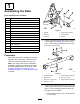
Setup Loose Parts Use the chart below to verify that all parts have been shipped. Procedure 1 2 3 Description Qty.
1 Assembling the Rake Parts needed for this procedure: 1 Tooth rake assembly 1 Tube tongue assembly 1 Clevis pin 2 Washer 1 Cotter pin 1 Bolt (1/2 x 1–3/4 inch) 1 Flange-head nut (1/2 inch) 1 Hex nut (1/2 inch) 1 Flange-head bolt (3/8 x 1 inch) 1 Flange-head nut (3/8 inch) 1 Attachment adapter assembly 2 Cotter pin 1 Lift arm assembly 1 Pivot bar 1 Bolt (3/8 x 1-1/4 inches) 1 Locknut (3/8 inch) g019663 Figure 3 1. Washer 4. Tongue tube assembly 2. Clevis pin 5.
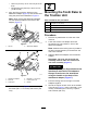
• Hex nut (1/2 inch)—91 to 113 N∙m (67 to 83 2 ft-lb) • Flange-head nut (3/8 inch)—22 to 27 N∙m (16 to 20 ft-lb) 4. Mounting the Tooth Rake to the Traction Unit Align the lift arm with the bracket on the attachment adapter (Figure 5) and connect them using the pivot bar as illustrated in Figure 6. Note: When moving the attachment adapter, Parts needed for this procedure: use the handle provided on the back of the adapter (Figure 5).
g220791 Figure 7 1. Tube frame of the traction unit 2. Long arm of the lift arm assembly 5. Spacer 3. Bolt (3/8 x 2-1/2 inches) 7. Locknut (3/8 inch) g220790 Figure 8 6. Chain 4. Washer (3/8 x 7/8 inch) 1. Jam nut 4. Lift-yoke shoulder 2. Adjustment nut 5. Heavy washer 3. 1.5 to 2 mm (0.060 to 0.080 inch) Note: For proper operation of the rake, the chains must be slack when the rake is in the lowered (operating) position. 3.
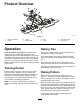
Product Overview g220789 Figure 9 1. Attachment adapter 3. Lift arm 5. Prong 7. Tooth rake hanger 2. Handle 4. Finishing rake 6. Trowel 8. Locking lever Operation Raking Tips Read this section on raking before raking a trap. There are many conditions that determine the adjustments to the tooth-rake attachment. The texture and depth of the sand, moisture content, weeds, and the amount of compaction all can vary from course to course, or even from trap to trap at the same course.
Adjusting the Rake Angle You can change the angle of the rake to increase or decrease its aggressiveness in the sand. Determine the desired aggressiveness required and mount the hitch assembly and tongue tube, as shown in the following figures, to attain the aggressiveness. Setting the Least Amount of Tine Engagement g003409 Figure 10 1. Enter a trap straight into the long dimension in a level area. 2. Exit a trap at a right angle in a level area.
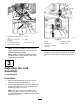
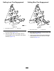
Setting More Tine Engagement Setting Less Tine Engagement g019668 Figure 12 1. Stop bracket lower hole g019666 Figure 13 2. Tongue tube 1. Stop bracket top hole 2. Tongue tube 1. Mount the hitch assembly in the lower holes of the stop bracket (Figure 12). 1. 2. Align the longer side of the tongue tube up and assemble it to the underside of the hanger assembly (Figure 12). Mount the hitch assembly in the top holes of the stop bracket (Figure 13). 2.
Setting the Maximum Amount of Tine Engagement g003411 Figure 15 1. Trowel Adjusting the Rake Stop Bolts g019667 Figure 14 1. Stop bracket lower hole 2. Tongue tube 1. Mount the hitch assembly in the lower holes of the stop bracket (Figure 14). 2. Align the longer side of the tongue tube down and assemble it to the top side of the hanger assembly (Figure 14). 2. Mounting screws Loosen the jam nuts and rotate the rake stop bolts (Figure 16) out to limit the side to side pivoting of the rake.
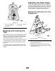
Using Drag Weights Inspecting and Cleaning the Rake and Traction Unit You can attach optional weights onto the finishing rakes if the sand is damp or coarse or if there are deep footprints in the traps. Order Part No. 18-7570 from your authorized Toro distributor. After raking, clean the machine thoroughly. Because you use this machine primarily in sand and sand is extremely abrasive, wash off the sand after each use.
Maintenance Greasing the Attachment Adapter If the locking lever on the attachment adapter does not pivot freely and easily, apply a light coat of grease to the area shown in Figure 18.
Notes:
Notes:
The Toro Warranty A Two-Year Limited Warranty Conditions and Products Covered The Toro Company and its affiliate, Toro Warranty Company, pursuant to an agreement between them, jointly warrant your Toro Commercial product (“Product”) to be free from defects in materials or workmanship for two years or 1500 operational hours*, whichever occurs first. This warranty is applicable to all products with the exception of Aerators (refer to separate warranty statements for these products).