
Operator's Manual
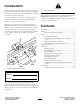

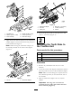
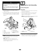

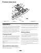
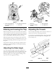
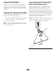

Figure3
1.Shoulderbolt4.Washer(0.469x0.922)
2.Washer(0.531x1.063)5.Locknut(7/16inch)
3.Pivotassembly6.Toothrakehanger
2.Aligntheliftarmwiththebracketontheattachment
adapter(Figure4)andconnectthemusingthepivot
barasillustratedinFigure5.
Note:Whenmovingtheattachmentadapter,use
thehandleprovidedonthebackoftheadapter
(Figure5).
Figure4
1.Liftarm
2.Attachmentadapter
Figure5
1.Attachmentadapter
4.Bolt(3/8x1-1/4inches)
2.Pivotbar
5.Locknut(3/8inch)
3.Cotterpins
6.Handle
3.Securethepivotbarwith2cotterpinsandabolt
(3/8x1-1/4inches)(Figure5).
2
MountingtheToothRaketo
theTractionUnit
Partsneededforthisprocedure:
2
Bolt(3/8x2-1/2inches)
4
Washer(3/8x7/8inch)
2
Spacer
2
Locknut(3/8inch)
Procedure
1.Removeanyattachmentfromtherearofthe
machine.
2.Lowerthetractionunitadapterandbackthetraction
unitintopositioninfrontoftheattachmentadapter.
Note:Makesurethelockingleverispivotedtothe
left(unlockedposition)asviewedfromtherearof
themachine.
3.Slidetheattachmentadapterontothetraction
adapter.
Important:Thelongarmoftheliftarm
assemblymustbeunderthetractionunitrear
frameassembly(Figure6).
5