
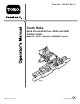
Operator's Manual


Ifyouarenotcareful,youcouldpinchyour
ngersbetweentheattachmentandtraction
unitadapters.
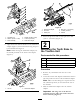
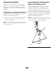
Alwaysliftandmovetheattachmentusingthe
handleonthebackoftheattachmentadapter
(Figure5).
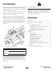
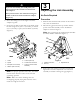
4.Pivotthelockinglevertotherighttolockthe
adapterstogether.
5.Securethetoplinkofeachchaintotheinsideofthe
liftarmusingabolt(3/8x2-1/2inches),2washers
(3/8x7/8inch),aspacer,andalocknut(3/8inch)
(Figure6).
Figure6
1.Chain5.Locknut(3/8inch)
2.Spacer6.Tractionunitrearframe
3.Bolt(3/8x2-1/2inches)7.Longarmoftheliftarm
assembly
4.Washer(3/8x7/8inch)
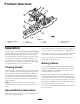
Note:Forproperoperationoftherake,thechains
mustbeslackwhentherakeisinthelowered
(operating)position.
Note:Makesureallthenishingrakesare
overlappingproperly,layingatandnoneofthe
chainsaretangledortwisted.
3
AdjustingtheLinkAssembly
NoPartsRequired
Procedure
1.Withtherakemountedandsecuredonthetraction
unit,raisetheattachment.
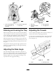
2.Measurethegapbetweenthetopwasherandthe
spacerinthelinkassemblyontheattachment
adapterasshowninFigure7.
Note:Thegapbetweenthewasherandtheshoulder
shouldbe0.060to0.080inch(Figure7).
Figure7
1.0.060to0.080inch3.Adjustmentnut
2.Jamnut
3.Ifthegapisnotcorrect,loosenthejamnutand
tightenorloosentheadjustmentnutonthelink
assemblyasneededtochangethegap(Figure7).
6