Form No. 3390-574 Rev A Debris Blower Sand Pro®/Infield Pro® 3040 and 5040 Traction Unit Model No. 08759—Serial No. 315000001 and Up Register at www.Toro.com.
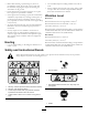
WARNING Model No. CALIFORNIA Proposition 65 Warning This product contains a chemical or chemicals known to the State of California to cause cancer, birth defects, or reproductive harm. Serial No. This manual identifies potential hazards and has safety messages identified by the safety alert symbol (Figure 2), which signals a hazard that may cause serious injury or death if you do not follow the recommended precautions. Introduction Figure 2 1.
Safety • Evaluate the terrain to determine what accessories and attachments are needed to properly and safely perform the job. Only use accessories and attachments approved by the manufacturer. Improperly using or maintaining the machine can result in injury. To reduce the potential for injury, comply with these safety instructions and always pay attention to the safety alert symbol , which means Caution, Warning, or Danger—personal safety instruction.
• Do not operate the machine under the influence of • Using the machine demands attention. To prevent tipping • • • • • • • • • • • • or loss of control: – Watch for holes or other hidden hazards. – Use caution when operating the machine on a steep slope. Reduce your speed when making sharp turns or when turning on hillsides. – Avoid sudden stops and starts. Do not go from reverse to full forward without first coming to a complete stop.
• Use full width ramps for loading machine into trailer or • Before disconnecting or performing any work on • • • • the hydraulic system, all pressure in the system must be relieved by stopping the engine and lowering the attachments to the ground. Check all fuel lines for tightness and wear on a regular basis. Tighten or repair them as needed.
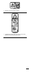
106-5517 1. Warning—do not touch the hot surface. 105-4593 1. Entanglement hazard, shaft—do not remove cover while parts are moving, keep all guards in place.
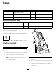
Setup Loose Parts Use the chart below to verify that all parts have been shipped. Procedure Description 1 2 3 Use Qty. Debris blower assembly 1 Mount the debris blower to the traction unit. No parts required – Adjust the link assembly. No parts required – Grease the blower. Media and Additional Parts Description Use Qty. Operator's Manual 1 Review the manual before operating the machine. Parts Catalog 1 Use the parts catalog to reference product part numbers.
Important: Whenever the hydraulic hose couplers are disconnected, make sure that the dust plugs are installed to prevent contamination from entering either hydraulic system. 3 Greasing the Blower 2 No Parts Required Adjusting the Link Assembly Procedure Before you operate the debris blower, grease it to ensure proper lubrication. Refer to Lubricating the Debris Blower (page 11). Failure to properly grease the machine will result in premature failure of critical parts. No Parts Required Procedure 1.
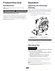
Product Overview Operation Specifications Adjusting the Discharge Opening Note: Specifications and design are subject to change without notice. Net weight You can adjust the discharge opening (Figure 5) to increase or decrease the air output velocity and volume. Decreasing the discharge opening size increases the velocity. Increasing the discharge opening size decreases the velocity. 107 kg (235 lb) Attachments/Accessories 1. Loosen the discharge opening deflector mounting screws (Figure 5).
1 G003783 Figure 6 1.
Maintenance Aligning the Bearings Lubricating the Debris Blower If the motor mounting brackets are ever removed, they must be realigned before the debris blower is operated. Refer to the Parts Catalog for the Alignment Tool part number. The debris blower has (2) fan shaft bearings that must be lubricated regularly. The bearings are located on each side of the blower housing.
Torquing the Fasteners If the blower is ever disassembled, the following fasteners must be torqued as specified. Also, apply removable thread-locking compound to the threads before installing the fasteners. • Torque the setscrews securing the motor and fan shaft couplers (Figure 10) to 6.6 to 9.3 N-m (58 to 82 in-lb). • Torque the fan shaft bearing setscrews (Figure 11) to 6.6 to 9.3 N-m (58 to 82 in-lb). G003816 1 Figure 11 1.
Notes: 13
Notes: 14
Declaration of Incorporation Model No. Serial No. Product Description Invoice Description General Description Directive 08759 315000001 and Up Debris Blower DEBRIS BLOWER Scarifier 2006/42/EC Relevant technical documentation has been compiled as required per Part B of Annex VII of 2006/42/EC. We will undertake to transmit, in response to requests by national authorities, relevant information on this partly completed machinery. The method of transmission shall be electronic transmittal.
Toro General Commercial Product Warranty A Two-Year Limited Warranty Conditions and Products Covered The Toro Company and its affiliate, Toro Warranty Company, pursuant to an agreement between them, jointly warrant your Toro Commercial product (“Product”) to be free from defects in materials or workmanship for two years or 1500 operational hours*, whichever occurs first. This warranty is applicable to all products with the exception of Aerators (refer to separate warranty statements for these products).