
Installation Instructions


AssemblingandInstallingthe
Lift-ArmAssembly
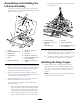
1.Attachthewearpadtothelift-armwith2hex-head
angebolts(3/8x1-1/4inches)and2angenuts(3/8
inch)asshowninFigure2.
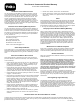
Figure2
1.Liftarm7.Flangenut(5/16inch)
2.Hex-headangebolt(2)8.Liftbeam
3.Carriagebolt
9.Wearpad
4.Connectionlift10.Flangenut—3/8inch(2)
5.Chain11.Hex-head-angebolt—3/8
x1-1/4inches(2)
6.Flatwasher(3/8inch)12.Cotterpins—5/32x1-1/4
inches
2.Sliptheconnectionliftovertheliftbeamandattachthe
chaintotheendoftheconnectionliftwithacarriage
bolt(5/16x1inch),aatwasher(3/8inch),anda
angenut(5/16inch);refertoFigure2.
3.Securetheliftbeam(withtheconnectionliftand
chain)totheliftarmwith2hex-head-angebolts(3/8
x1-1/4inches)asshowninFigure2.
4.Install2cotterpins(5/32x1-1/4inches)inthelift
beaminthelocationsshowninFigure2.
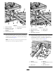
5.Installthelift-armassemblyontothequick-attach
couplerasfollows:
A.Inserttheendofthepivotbarthroughtheright
sideoftheliftarm,slipaangebearingoverthe
endofthepivotbar,pushtheliftbeamthrough
therightarmofthequick-attachcoupler,slip
anotherangebearingovertheendofthepivot
bar,andfullyinsertthepivotbartotheleftarm
ofthequick-attachcouplertotheleftsideofthe
liftarm(Figure3).
Figure3
1.Lift-armassembly
4.Pivotbar
2.Cotterpin—5/32x1-1/4
inches(3)
5.Flangenut(3/8inch)
3.Flangebearing(2)6.Hex-head-angebolt(3/8
x1–1/4inches)
B.Securethepivotbarandthelift-armwitha
hex-head-angebolt(3/8x1-1/4inches)anda
angenut(3/8inch)asshowninFigure3.
C.Install3cotterpins(5/32x1-1/4inches)inthe
pivotbarinthelocationsshowninFigure3.
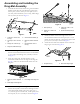
InstallingtheDragTongue
1.Installthefrontendofthedragtongueandthe
slide-lockbracketontothenail-dragbracketwitha
clevispin(1/2x4-1/2inches),aatwasher(17/32
inch),andacotterpin(1/8x1inch)asshownin
Figure4.
Note:Inserttheclevispinthroughthemiddleholes
intheslide-lockbracket(Figure4).
3