
Installation Instructions


AssemblingandInstallingthe
Drag-MatAssembly
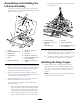
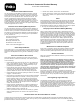
1.Assemblethemat-bracketframeusing2crossmember
bracketsand2drag-mat,sidebracketstogetherwith
2clevispins(3/8x3/4inch),2cotterpins(15/16x
3/4inch),2hex-headbolts(3/8x1inch),and2ange
nuts(3/8inch)asshowninFigure7.
Figure7
1.Cotterpin—15/16x3/4
inch(2)
5.Crossmemberbracket(2)
2.Clevispin—3/8x3/4inch
(2)
6.Drag-mat,bottombracket
(3)
3.Flangenut—3/8inch(5)7.Hex-headbolt—3/8x1
inch(5)
4.Drag-mat,sidebracket(2)
2.Attachthe3drag-mat,bottombracketsontotherear,
bottomofthemat-bracketframewith3hex-headbolts
(3/8x1inch)and3angenuts(3/8inch)asshown
inFigure7.
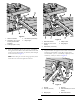
3.Insertthe3drag-mat,bottombracketsonthe
mat-bracketframeintotherearedgeofthedragmat
(Figure7)andlowerthemat-bracketframeontothe
dragmat.
g029879
1
2
3
Figure8
1.Drag-mat,bottombracket
(3)
3.Frontedgeofthedragmat
2.Rearedgeofthedragmat
4.Securethefrontedgeofthedragmatandtheeyelet
endsofthelanyardstothefrontleftandrightcorners
ofthemat-bracketframewith2clevispins(3/8x
1-1/8inches)upfromthebottom,2zincspacers,and
2cotterpins(15/16x3/4inch)asshowninFigure9.
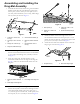
Figure9
1.Zincspacer(3)3.Clevispin—3/8x1-1/8
inches(3)
2.Cotterpin—15/16x3/4
inch(3)
4.Eyeletendoflanyard(2)
5.Attachthecenterofthefrontedgeofthematto
themat-bracketframewithaclevispin(3/8x1-1/8
inches)upfromthebottom,azincspacer,andacotter
pin(15/16x3/4inch)asshowninFigure9.
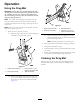
6.Attachthefreeendsofthelanyardstotheendofthe
dragtongueasshowninFigure10.
Figure10
1.Lanyardend(2)2.Endofthedragtongue
5