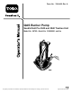
Form No. 3364-409 Rev A QAS Bunker Pump Sand/Infield Pro 3040 and 5040 Traction Unit Model No. 08765—Serial No. 310000001 and Up To register your product or download an Operator's Manual or Parts Catalog at no charge, go to www.Toro.com.
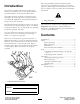
This manual identifies potential hazards and has safety messages identified by the safety alert symbol (Figure 2), which signals a hazard that may cause serious injury or death if you do not follow the recommended precautions. Introduction This product complies with all relevant European directives, for details please see the separate product specific Declaration of Conformity (DOC) sheet.
Safety • Using the machine demands attention. To prevent loss of control: – Operate only in daylight or when there is good artificial light. – Drive slowly and watch for holes or other hidden hazards. – Use extreme caution when driving into a sand trap, ditch, creek, or other hazard. – Reduce your speed when making sharp turns and when turning on hillsides. – Avoid sudden starts and stops. – Before backing up, look to the rear and ensure that no one is behind the machine.
• Make sure that all hydraulic line connectors are tight and all hydraulic hoses and lines are in good condition before applying pressure to the system. and other parts of the body away from the fan and other moving parts. • Do not overspeed the engine by changing the governor settings. To be sure of safety and accuracy, have an Authorized Toro Distributor check the maximum engine speed with a tachometer.
Setup Loose Parts Use the chart below to verify that all parts have been shipped. Procedure Description 1 2 Use Qty. Bunker pump assembly 1 Mount the bunker pump to the traction unit No parts required – Adjust the link assembly Media and Additional Parts Description Use Qty.
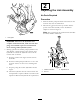
2 Adjusting the Link Assembly No Parts Required Procedure 1. With the bunker pump mounted and secured on the traction unit, raise the attachment. 1 2. Measure the gap between the top washer and the spacer in the link assembly on the attachment adapter as shown in Figure 5. Note: The gap between the washer and the shoulder should be 0.060 to 0.080 inch G008127 Figure 4 1.
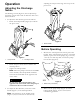
Operation adjusting the torque on the large nut on top of the pivot tower. Adjusting the Discharge Nozzle 1 The discharge nozzle (Figure 6) can be adjusted up and down or from side to side to direct the flow to the desired location. 1. To adjust the flow distance, proceed as follows • Rotate the lockup handle (Figure 6) to unlock the pivot tower. 2 1 G008120 Figure 7 1. Nozzle handle Before Operating 1. Measure the water depth in the lowest part of the bunker.
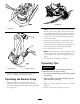
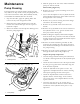
1 G008122 Figure 11 Figure 9 1. Pump clamp Note: If the Sand Pro cannot be moved into the desired position, the pump can be removed from the housing and placed into the water. To remove the pump, pivot the pump clamp forward, slide the pump to the rear of the frame and lift the pump out with the handle. 2 2. Start the remote hydraulics to activate the pump before inserting the pump into the water. This prevents debris from stalling the pump impeller to the housing if debris gets lodged in the pump.
Note: If the attachment adapter becomes stuck to the traction unit adapter, insert a pry bar/screwdriver into the pry slot to disengage the parts (Figure 12). 1 G003783 Figure 12 1.
Maintenance 5. Slide the pump to the rear of the frame and lift the pump out with the handle. Disassembly (Figure 15) Pump Cleaning 6. Remove the (5) cover plate mounting screws and remove the cover. If foreign matter gets into the bunker pump, the flow may decrease or stop. If this occurs, the pump will have to be removed from the frame, disassembled, cleaned, reassembled and installed back into the frame. 7. Try to turn the impeller to free any debris from the pump impeller and housing.
Figure 15 1. Cover plate 2. Suction flange 3. Impeller 4. Shaft 5. Pump housing 6. Thrust plate Reassembly (Figure 15) 7. Hydraulic motor 8. Handle bottom of the shoulder in the body. Install the snap ring to secure the shaft assembly. 1. Press the new lip seals into the pump housing using a suitable bushing or socket. A light lubricant may be used to aid the assembly. The proper assembly is to install the seals back to back, installing one seal at a time. 4.
over the shaft and stopping at the thrust plate. Line up the gerotor and thrust plate. 7. Install the cover onto the shaft; some sideways movement of the gerotor is necessary. The dowel pins should go through the thrust plate and into the body. Do not force this assembly by using a hammer or press, it will slide together when it is in position. 1 8. Install the four motor cover screws and torque to 17-ft.lbs in a cross pattern with the first torque @ 10-ft.lbs. 9. Install the suction flange and screws.
Notes: 13
Notes: 14
Notes: 15
The Toro Total Coverage Guarantee A Limited Warranty Conditions and Products Covered The Toro® Company and its affiliate, Toro Warranty Company, pursuant to an agreement between them, jointly warrant your Toro Commercial product (“Product”) to be free from defects in materials or workmanship for two years or 1500 operational hours*, whichever occurs first. This warranty is applicable to all products with the exception of Aerators (refer to separate warranty statements for these products).