Form No. 3392-914 Rev A QAS Bunker Pump Sand Pro®/Infield Pro® 3040 and 5040 Traction Unit Model No. 08765—Serial No. 315000001 and Up Register at www.Toro.com.
The bunker pump is mounted to a Sand Pro machine and is intended to be used by professional, hired operators in commercial applications. It is primarily designed to pump water out of sand traps. This product complies with all relevant European directives. For details, please see the Declaration of Incorporation (DOI) at the back of this publication.
Safety Before Operating .................................................... 7 Operating the Bunker Pump ..................................... 8 Operating Tips........................................................ 8 Maintenance .................................................................10 Pump Cleaning ......................................................
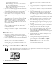
• • • • • Never wash a warm engine or any electrical parts with water. – Avoid sudden starts and stops. – Before backing up, look to the rear and ensure that no one is behind the machine. – Watch out for traffic when near or crossing roads. Always yield the right-of-way. Stay away from the discharge opening when the machine is operating. Keep all bystanders away from the discharge opening and don’t direct discharge toward bystanders.
Setup Loose Parts Use the chart below to verify that all parts have been shipped. Procedure Description 1 2 Use Qty. Bunker pump assembly 1 Mount the bunker pump to the traction unit. No parts required – Adjust the link assembly. Media and Additional Parts Description Use Qty.
2 Adjusting the Link Assembly No Parts Required Procedure 1. With the bunker pump mounted and secured on the machine, raise the attachment. 1 2. Measure the gap between the top washer and the spacer in the link assembly on the attachment adapter as shown in Figure 5. Note: Ensure the gap between the washer and the shoulder is between 1.52 to 2.03 mm (0.060 to 0.080 inch). G008127 Figure 4 1.
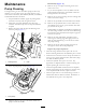
Operation 1 Adjusting the Discharge Nozzle The discharge nozzle (Figure 6) can be adjusted up and down or from side to side to direct the flow to the desired location. 1. To adjust the flow distance, proceed as follows • Rotate the lockup handle (Figure 6) to unlock the pivot tower. 2 G008120 1 Figure 7 1. Nozzle handle Before Operating 1. Measure the water depth in the lowest part of the bunker. If the water depth is less than 63.5 mm (2–1/2 inches) (halfway up the slots on the pump), dig a 30.
1 G008122 Figure 11 Figure 9 1. Pump clamp Note: If the Sand Pro machine cannot be moved into the desired position, the pump can be removed from the housing and placed into the water. To remove the pump, pivot the pump clamp forward, slide the pump to the rear of the frame and lift the pump out with the handle. 2 2. Start the remote hydraulics to activate the pump before inserting the pump into the water.
Note: If the attachment adapter becomes stuck to the traction unit adapter, insert a pry bar/screwdriver into the pry slot to disengage the parts (Figure 12). 1 G003783 Figure 12 1.
Maintenance Disassembly (Figure 15) 6. Remove the (5) cover plate mounting screws and remove the cover. Pump Cleaning 7. Try to turn the impeller to free any debris from the pump impeller and housing. If the debris cannot be freed, proceed to the next step. If foreign matter gets into the bunker pump, the flow may decrease or stop. If this occurs, the pump will have to be removed from the frame, disassembled, cleaned, reassembled and installed back into the frame. 1.
Figure 15 1. Cover plate 3. Impeller 5. Pump housing 7. Hydraulic motor 2. Suction flange 4. Shaft 6. Thrust plate 8. Handle Reassembly (Figure 15) 1. Press the new lip seals into the pump housing using a suitable bushing or socket. A light lubricant may be used to aid the assembly. The proper assembly is to install the seals back to back, installing one seal at a time. 2.
Do not force this assembly by using a hammer or press, it will slide together when it is in position. 8. Install the four motor cover screws and torque to 23.0 N-m (17 ft-lb) in a cross pattern with the first torque at 13.6 N-m (10 ft-lb). 9. Install the suction flange and screws. 10. Install the handle and screws. 1 11. Check for free rotation by rotating the impeller by hand. If it does not rotate, remove the motor cover, clean the motor parts, and reassemble.
Notes: 13
Declaration of Incorporation Model No. 08765 Serial No. Product Description Invoice Description General Description Directive 315000001 and Up QAS Bunker Pump, Sand Pro/Infield Pro 3040 and 5040 Traction Unit QAS BUNKER PUMP Bunker Pump 2006/42/EC Relevant technical documentation has been compiled as required per Part B of Annex VII of 2006/42/EC. We will undertake to transmit, in response to requests by national authorities, relevant information on this partly completed machinery.
International Distributor List Distributor: Country: Phone Number: Distributor: Phone Number: 57 1 236 4079 Colombia Japan 81 3 3252 2285 Czech Republic 420 255 704 220 420 255 704 Slovakia 220 Argentina 54 11 4 821 9999 Russia 7 495 411 61 20 Ecuador 593 4 239 6970 Finland 358 987 00733 Agrolanc Kft Balama Prima Engineering Equip. B-Ray Corporation Hungary Hong Kong Korea 36 27 539 640 852 2155 2163 82 32 551 2076 Maquiver S.A. Maruyama Mfg. Co. Inc. Mountfield a.s.
Toro General Commercial Product Warranty A Two-Year Limited Warranty Conditions and Products Covered The Toro Company and its affiliate, Toro Warranty Company, pursuant to an agreement between them, jointly warrant your Toro Commercial product (“Product”) to be free from defects in materials or workmanship for two years or 1500 operational hours*, whichever occurs first. This warranty is applicable to all products with the exception of Aerators (refer to separate warranty statements for these products).