Form No. 3367-526 Rev A Sports Field Edger Sand/Infield Pro 3040 and 5040 Traction Unit Model No. 08766—Serial No. 311000001 and Up To register your product or download an Operator's Manual or Parts Catalog at no charge, go to www.Toro.com.
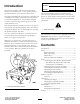
Model No. Introduction Serial No. This product complies with all relevant European directives, for details please see the separate product specific Declaration of Conformity (DOC) sheet. This manual identifies potential hazards and has safety messages identified by the safety alert symbol (Figure 2), which signals a hazard that may cause serious injury or death if you do not follow the recommended precautions.
Safety • Using the machine demands attention. To prevent loss of control: Hazard control and accident prevention are dependent upon the awareness, concern, and proper training of the personnel involved in the operation, transport, maintenance, and storage of the machine. Improper use or maintenance of the machine can result in injury or death. To reduce the potential for injury or death, comply with the following safety instructions. – Operate only in daylight or when there is good artificial light.
• Keep your body and hands away from pin hole leaks in hydraulic lines that eject high pressure hydraulic fluid. Use cardboard or paper to find hydraulic leaks. Hydraulic fluid escaping under pressure can penetrate skin and cause injury. Fluid accidentally injected into the skin must be surgically removed within a few hours by a doctor familiar with this form of injury or gangrene may result.
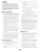
Safety and Instructional Decals Safety decals and instructions are easily visible to the operator and are located near any area of potential danger. Replace any decal that is damaged or lost. 120-3450 1. Warning—read the Operator’s Manual, keep bystanders a safe distance from the machine. 2. Cutting hazard of hand and foot, edger—keep hands and feet away from moving parts, keep all guards and shields in place.
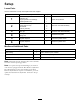
Setup Loose Parts Use the chart below to verify that all parts have been shipped. Procedure Description 1 2 3 4 5 6 Use Qty.
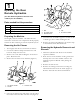
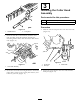
4 1 5 1 Updating the Rear Remote Hydraulics 2 (For Rear Remote Hydraulics Kits with serial numbers prior to 310000001) 3 Parts needed for this procedure: G003580 1 Small tee fitting 1 Hydraulic cap 1 Large hydraulic hose w/fittings 1 Small hydraulic hose Figure 4 1. Bolt 2. Air cleaner strap 3. Machine frame 4. Cap 5. Air cleaner canister Preparing the Machine 7. Cover the hose or install a rag into it so that no dirt or debris gets into it while installing this kit.
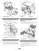
Figure 7 Figure 5 1. Left hand wheel shroud 2. Flange-head screws 1. Hydraulic tank 2. Bolt 3. Top bracket 3. Tire 4. Nut 5. Remove the 2 flange-head screws securing the left front screen to the frame (Figure 6). Remove and retain the screen and hardware. 4. Nut 5. Side bracket 6. Washer Installing the New Hydraulic Components 1. Disconnect the short hydraulic line from the coupler fitting and the hydraulic line port (Figure 8). 1 2 3 G003836 Figure 6 1. Flange-head screws 2. Frame 3.
4. Install the new small tee fitting into the hydraulic tank. Position the fitting as shown in Figure 9. 1. When all hydraulic lines and hoses are installed, tighten all of the connections. 2. Use a backup wrench on all tank fittings. Install the Screen, Shrouds and Tire 1. Install the left front screen to the frame. 2. Install the front shroud to the frame with 4 flange-head screws. 3. Install the 4 flange-head screws securing the left-hand wheel shroud to the frame. 4. Install the left rear tire 5.
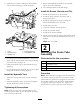
3 Installing the Cutter Head Assembly Parts needed for this procedure: 1 Cutter head assembly 1 Hitch pin Procedure Figure 10 1. Saddle bracket 1. Slide the cutter head pivot tube onto the cross tube (Figure 12). 2. Foot guard 1. From the left side of the machine, slide the cross tube assembly under the machine, aligning the mounting bracket holes with the holes in each frame tube (Figure 11). Figure 12 Figure 11 1. Cross tube 2. Hitch pin 1. Cross tube assembly 3. Cutter head 2.
4 Installing the Hose Guide Parts needed for this procedure: 1 Hose guide 1 Flange nut Procedure Figure 14 1. Remove the bolt, washer and nut securing the top hydraulic tank clamp to the frame (Figure 13). Remove and discard the clamp, bolt, washer and nut. 1. Hydraulic hoses 2. Hose guide Note: The hydraulic tank clamp may have been removed in a previous step. 3. Rear remote connectors 2. Connect the hoses to the rear remote connectors (Figure 14).
Product Overview Controls Handle The handle is used to raise and lower the edger (Figure 17). Figure 15 1. Oil reservoir cap 4. Remove the cap from the reservoir 5. Remove the dipstick from filler neck and wipe it with a clean rag. 6. Insert the dipstick into the filler neck; then remove it and check the level of the fluid. Note: The fluid level should be up to the mark (necked down area) on the dipstick (Figure 16). Figure 17 1.
Operation Note: Determine the left and right sides of the machine from the normal operating position. Operating the Edger 1. Start the engine. 2. Press outward on the handle and lower the edger blade to the ground (Figure 17). 3. Engage the blade by pulling up on the Remote Hydraulics control knob (Figure 19). Figure 20 1. Roller 2. Roller shaft 3. Scraper rod 4. Remove the roller shaft from the roller (Figure 20). 5. Move the roller to the desired depth and install the shaft.
Maintenance Note: Determine the left and right sides of the machine from the normal operating position. Lubrication The edger cutter head has a grease fitting that must be lubricated with No. 2 General Purpose Lithium Base Grease after every 100 hours of operation (Figure 21). Figure 22 1. Blade width 2. Edger blade 4. Install the new blade with the screws and nuts previously removed.
Storage • Thoroughly wash the machine with a garden hose-without a nozzle-so that excessive water pressure will not cause contamination and damage to the seals and bearing • Check all fasteners for looseness; tighten as necessary. • Grease the fitting. Wipe off any excess lubricant • Check the edger blade and replace as required.
The Toro Total Coverage Guarantee A Limited Warranty Conditions and Products Covered The Toro® Company and its affiliate, Toro Warranty Company, pursuant to an agreement between them, jointly warrant your Toro Commercial product (“Product”) to be free from defects in materials or workmanship for two years or 1500 operational hours*, whichever occurs first. This warranty is applicable to all products with the exception of Aerators (refer to separate warranty statements for these products).