Form No. 3394-543 Rev A Sports Field Edger Sand Pro® 3040 and 5040 Traction Unit Model No. 08766—Serial No. 315000201 and Up Register at www.Toro.com.
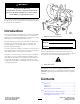
WARNING CALIFORNIA Proposition 65 Warning This product contains a chemical or chemicals known to the State of California to cause cancer, birth defects, or reproductive harm. This product complies with all relevant European directives. For details, please see the Declaration of Incorporation (DOI) at the back of this publication. Introduction This kit is mounted to a Sand Pro traction unit and is intended to be used by professional, hired operators in commercial applications.
Safety 4 Routing the Hydraulic Hoses .................................. 8 5 Checking the Hydraulic Fluid.................................. 8 Product Overview .........................................................10 Controls ...............................................................10 Operation ....................................................................10 Operating the Edger ...............................................10 Adjusting the Edger Blade Depth .............................
• • • • • Do not overspeed the engine by changing the governor – Reduce your speed when making sharp turns and when turning on hillsides. – Avoid sudden starts and stops. – Before backing up, look to the rear and ensure that no one is behind the machine. – Watch out for traffic when near or crossing roads. Always yield the right-of-way. If the engine stalls or the machine loses headway and cannot make it to the top of a slope, do not turn the machine around. Always back slowly straight down the slope.
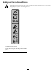
Safety and Instructional Decals Safety decals and instructions are easily visible to the operator and are located near any area of potential danger. Replace any decal that is damaged or lost. 120-3450 1. Warning—read the Operator's Manual, keep bystanders a safe distance from the machine. 2. Cutting hazard of hand and foot, edger—keep hands and feet away from moving parts, keep all guards and shields in place.
Setup Loose Parts Use the chart below to verify that all parts have been shipped. Procedure Description 1 2 3 4 5 Use Qty. Cross tube assembly Screw (3/8 x 3 inch) Flat washer Locknut (3/8 inch) Cutter-head assembly Hitch pin Hose guide Flange nut 1 4 4 4 1 1 1 1 No parts required – Route the hydraulic hoses. No parts required – Check the hydraulic fluid. Mount the cross tube assembly. Install the cutter-head assembly. Install the hose guide. Media and Additional Parts Description Use Qty.
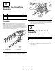
1 Mounting the Cross Tube Assembly Parts needed for this procedure: 1 Cross tube assembly 4 Screw (3/8 x 3 inch) 4 Flat washer 4 Locknut (3/8 inch) Figure 4 1. Cross tube assembly Procedure 2. Secure the cross tube mounting brackets to the frame tubes with 4 screws (3/8 x 3 inch), 4 flat washers, and 4 locknuts (3/8 inch); refer to Figure 4.
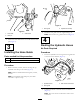
Figure 6 1. Hose guide Figure 5 1. Cross tube 2. Hitch pin 2. Install the hose guide with the supplied flange nut. 3. Cutter head Note: Position the hose guide as shown in Figure 6. 4 2. Secure the cutter head to the cross tube with the hitch pin (Figure 5). Routing the Hydraulic Hoses 3 No Parts Required Installing the Hose Guide Procedure 1. Route the hydraulic hoses through the hose guide and to the rear of the machine (Figure 7).
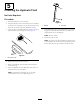
5 Checking the Hydraulic Fluid No Parts Required Procedure 1. Park the machine on a level surface. Figure 9 2. Stop the machine, move the throttle control to the Slow position, rotate the ignition key to Off, and remove the key from the switch to prevent accidental starting. 1. Dipstick 3. Clean the area around the hydraulic oil-reservoir cap to prevent debris from entering the tank (Figure 8). 2. Full mark 7.
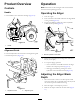
Product Overview Operation Controls Note: Determine the left and right sides of the machine from the normal operating position. Handle Operating the Edger Use the handle to raise and lower the edger (Figure 10). 1. Start the engine. 2. Press outward on the handle and lower the edger blade to the ground (Figure 10). 3. Engage the blade by pulling the remote hydraulics control knob upward (Figure 12). Figure 10 1.
Figure 13 1. Roller 3. Scraper rod 2. Roller shaft 4. Remove the roller shaft from the roller (Figure 13). 5. Move the roller to the desired depth and install the shaft. Start at the low setting 1/2 to 1-1/2 inches. Note: Moving the roller down will raise the cutting depth. 6. Lock the roller in position with the scraper rod. Using the Alignment Guide Use the alignment guide to keep the edger in a straight line by sight or when following a string line. 1.
Maintenance Note: Determine the left and right sides of the machine from the normal operating position. Lubricating the Edger The edger cutter head has a grease fitting that must be lubricated with #2 general-purpose, lithium-based grease after every 100 hours of operation (Figure 14). Figure 15 1. Blade width 2. Edger blade 4. Install the new blade with the screws and nuts previously removed.
Storage • Thoroughly wash the machine with a garden hose without a nozzle so that excessive water pressure will not cause contamination and damage to the seals and bearing. • Check all fasteners for looseness; tighten as necessary. • Grease the fittings. Wipe off any excess lubricant. • Check the edger blade and replace as required.
Declaration of Incorporation Model No. Serial No. Product Description Invoice Description General Description Directive 08766 315000001 and Up Sports Field Edger VIBRATORY EDGER, QAS Vibratory Edger 2006/42/EC Relevant technical documentation has been compiled as required per Part B of Annex VII of 2006/42/EC. We will undertake to transmit, in response to requests by national authorities, relevant information on this partly completed machinery.
International Distributor List Distributor: Country: Phone Number: Distributor: Phone Number: 57 1 236 4079 Colombia Japan 81 3 3252 2285 Czech Republic 420 255 704 220 420 255 704 Slovakia 220 Argentina 54 11 4 821 9999 Russia 7 495 411 61 20 Ecuador 593 4 239 6970 Finland 358 987 00733 Agrolanc Kft Balama Prima Engineering Equip. B-Ray Corporation Hungary Hong Kong Korea 36 27 539 640 852 2155 2163 82 32 551 2076 Maquiver S.A. Maruyama Mfg. Co. Inc. Mountfield a.s.
Toro General Commercial Product Warranty A Two-Year Limited Warranty Conditions and Products Covered The Toro Company and its affiliate, Toro Warranty Company, pursuant to an agreement between them, jointly warrant your Toro Commercial product (“Product”) to be free from defects in materials or workmanship for two years or 1500 operational hours*, whichever occurs first. This warranty is applicable to all products with the exception of Aerators (refer to separate warranty statements for these products).