
Operator's Manual
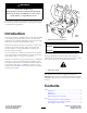
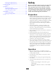
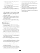
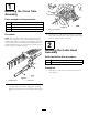
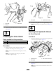
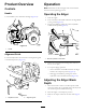

Figure5
1.Crosstube3.Cutterhead
2.Hitchpin
2.Securethecutterheadtothecrosstubewiththehitch
pin(Figure5).
3
InstallingtheHoseGuide
Partsneededforthisprocedure:
1Hoseguide
1Flangenut
Procedure
1.Removethebolt,washer,andnutsecuringthetop
hydraulictankclamptotheframe(Figure6).
Note:Removeanddiscardtheclamp,bolt,washer,
andnut.
Note:Thehydraulictankclampmayhavebeen
removedinapreviousstep.
Figure6
1.Hoseguide2.Hydraulictankclamp
2.Installthehoseguidewiththesuppliedangenut.
Note:PositionthehoseguideasshowninFigure6.
4
RoutingtheHydraulicHoses
NoPartsRequired
Procedure
1.Routethehydraulichosesthroughthehoseguideand
totherearofthemachine(Figure7).
Figure7
1.Hydraulichoses3.Rearremoteconnectors
2.Hoseguide
2.Connectthehosestotherearremoteconnectors
(Figure7).
Note:Thehosescanbeconnectedtoeitherofthe
connectors.
8