
Installation Instructions


Form No. 3356-421 Rev B
Rear Remote Hydraulic Kit
For Sand/Ineld Pro 3040 and 5040 Traction Unit
Model No. 08781
Installation Instructions
Note: Deter mine the left and right sides of the mac hine from the nor mal operating position.
Loose Parts
Use the chart below to verify that all parts have been shipped.
Step
Description
Qty.
Use
1
No parts required
–
Prepare the machine.
2
No parts required
–
Remove the air cleaner.
3
No parts required
–
Remove the hydraulic reservoir and
shrouds.
Small 90 degree elbow with barb
1
Large 90 degree elbow (threaded
both ends)
1
4
Strainer
1
Install ttings to the hydraulic tank.
Retainer bracket
1
Mufer clamp
2
Hose retainer bracket
1
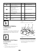
5
Coupler bracket
1
Install the coupler bracket to the
rear frame.
Valve
1
Valve plate
1
Bolt, (1/4 x 1–3/4 inches)
2
Nut, (1/4 inch)
2
Small 90 degree elbow
1
Tee tting
1
Tapping bolt, (9/32 x 3/4 inch)
2
Tee adapter
1
Relay
1
6
Cap
1
Install the manifold and bracket.
Hydraulic line number 1
1
Hydraulic line number 2
1
7
Hydraulic line number 5
1
Install the hydraulic lines.
Hydraulic pump
1
45 degree tting (male ends)
1
Hub assembly
1
Square key (1/4 x 1 inch)
1
Set screw, (5/16 x 3/4 inch)
4
Pump bracket
1
Bolt (with Loctite®), (5/16 x 3/4
inch)
2
8
Large 90 degree elbow (with hose
barbed end)
1
Install the hydraulic pump.
© 2006—The Toro® Company
8111 Lyndale Avenue South
Bloomington, MN 55420
Register at www.Toro.com. Original Instructions (EN)
Printed in the USA.
All Rights Reserved