Form No. 3369-227 Rev C Rear Remote Hydraulic Kit Sand Pro®/Infield Pro® 3040 and 5040 Traction Unit Model No. 08781—Serial No. 311000001 and Up Installation Instructions Note: Determine the left and right sides of the machine from the normal operating position. Loose Parts Use the chart below to verify that all parts have been shipped. Procedure 1 2 3 4 5 6 7 8 © 2014—The Toro® Company 8111 Lyndale Avenue South Bloomington, MN 55420 Description Qty.
Procedure Description Hydraulic line number 3 Hydraulic line number 4 Large hydraulic hose Hydraulic hose with fittings Large hose clamp Small hose clamp Small molded hydraulic hose R-clamp Bolt, (5/16 x 7/8 inch) Flange nut, (5/16 inch) 1 1 1 1 2 2 1 1 1 1 11 No parts required – 12 Harness Switch Fuse Dipstick 13 Hydraulic oil 9 10 Use Qty. 1 1 1 1 6–3/4 gallons (25.5 liters) Install the hydraulic lines. Install the hydraulic hoses. Tighten all connections. Install the switch and harness.
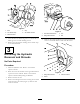
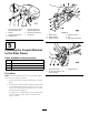
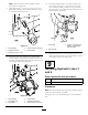
4 5 1 2 3 G003580 Figure 2 1. Bolt 4. Cap 2. Air cleaner strap 5. Air cleaner canister Figure 3 1. Left hand wheel shroud 2. Flange-head screws 3. Machine frame 7. Cover the hose or install a rag into it so that no dirt or debris gets into it while installing this kit. 3. Tire 4. Nut 5. Remove the 2 flange-head screws securing the left front screen to the frame. Remove and retain the screen. 8. Remove the opposite bolt holding the air cleaner strap to the machine frame.
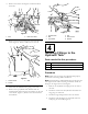
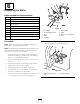
6. Remove the 3 bolts securing the rear hitch shield to the frame. Figure 7 Figure 5 1. Bolt 2. Rear hitch shield 1. Hydraulic tank 4. Nut 2. Bolt 3. Top bracket 5. Side bracket 6. Washer 7. Remove the 2 screws securing the center shroud to the frame (Figure 6). Remove and retain the shroud.
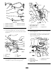
Figure 8 1. Large 90 degree elbow, install at angle shown 5. Small 90 degree tee, install at angle shown 2. Strainer 6. Remove the small plug 3. Remove the large plug 7. 45 degrees Figure 9 4. Hydraulic tank 1. Muffle clamp 4. Retainer bracket 2. Muffler bracket 3. Coupler bracket 5. Nut 6. Rear frame round tube 5 Installing the Coupler Bracket to the Rear Frame Parts needed for this procedure: 1 Retainer bracket 2 Muffler clamp 1 Hose retainer bracket 1 Coupler bracket Figure 10 1.
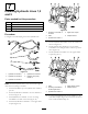
2 3 4 1 5 6 Installing the Valve Parts needed for this procedure: 9 1 Valve 1 Valve plate 2 Bolt, (1/4 x 1–3/4 inches) 2 Nut, (1/4 inch) 1 Small 90 degree elbow 1 Tee fitting 2 Tapping bolt, (9/32 x 3/4 inch) 1. Tee adapter 6. Valve bracket 1 Tee adapter 2. Small 90 degree elbow 7. Relay 1 Relay 3. Nut 8. Bolt, (1/4 x 1–3/4 inches) 4. Valve 1 9. Cap Cap 7 G003576 8 Figure 11 5. Tee fitting Procedure 7.
1 7 2 3 4 5 Installing Hydraulic Lines 1,2 and 5 Parts needed for this procedure: 1 Hydraulic cap 1 Hydraulic line number 1 1 Hydraulic line number 2 1 Hydraulic line (hose) number 5 G003608 Figure 14 Procedure 1. Tee fitting on the side of the valve 2. Valve Use Figure 13 for identifying the correct hydraulic lines. 3. Hydraulic line number 1 4. Upper male coupler 5. Coupler bracket 5. Position hydraulic line number 2 into the machine as shown in Figure 15. 6.
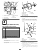
Figure 17 2. Coupler bracket 4. Male end 2. Hydraulic pump 5. Female end 3. Large 90 degree elbow (with hose barbed end) Figure 16 1. Hydraulic line number 1 1. 45 degree elbow 4. Hydraulic line (hose) number 5 5. Hydraulic cap 3. Remove the existing cover over the engine PTO (Power Take Off). 3. Lower male coupler 4. Install the pump bracket to the engine with 2 bolts (5/16 x 3/4 inch) and 2 washers (3/8 inch). Refer to Figure 18 for the correct position to install the pump bracket.
Note: Make sure that the hub assembly is totally bottomed out on the shaft. 10. The hub assembly needs to be totally seated on the shaft. Verify that there is a gap between the pump plate and hub assembly. If there is no gap, then the hub assembly is not installed correctly and needs to be seated correctly (Figure 21). 8. Apply blue Loctite® to the 2 set screws (5/16 x 3/4 inch) and install them into the hub assembly to secure it to the PTO shaft (Figure 19).
Figure 22 1. Hydraulic line number 1 4. Hydraulic line number 4 2. Hydraulic line number 2 5. Hydraulic line number 5 Figure 24 3. Hydraulic line number 3 1. Small 90 degree tee with barb in hydraulic tank 4. Tee fitting 2. Hydraulic line number 4 5. Hydraulic tank 3. Valve 1. Install the existing hoses back onto the hydraulic tank. 2. Install the hydraulic tank to the frame and secure it with the 3 brackets previously removed and loosened (Figure 23). 4.
6. Install a R-clamp onto the large hydraulic hose as shown in Figure 27. Install the R-clamp to the retainer bracket with a bolt (5/16 x 7/8 inch) and nut (5/16 inch) (Figure 27).
5 1 2 3 4 G003613 Figure 29 1. Tee adapter to the side of 3. 45 degree elbow the valve 2. Hydraulic hose with fittings 4. Hydraulic pump 9. Use Figure 30 for the correct locations of the hoses and hydraulic lines to the hydraulic pump. g018784 Figure 31 1. Small 90 degree tee with barb in hydraulic tank 4. Hydraulic line number 4 1 2. Small hose clamp 5. Hydraulic line (hose) number 5 2 3. Small molded hose 3 11 6 G003840 5 Tightening all Connections 4 No Parts Required Figure 30 1.
12 Installing the Switch and Harness Parts needed for this procedure: 1 Harness 1 Switch 1 Fuse Procedure 1. Remove the control panel from the machine. 2. Remove the plastic plug from the panel and install the switch to the panel (Figure 34). Figure 33 3. Route the harness along the seat hinge from the switch and to the relay previously installed to the valve (Figure 32). 1. Main harness connector 2. Jumper wire 6. Install the main harness connector to the main harness (Figure 34). 7 7.
3 4 1 5 2 6 Figure 36 G003620 1. Hydraulic tank cap 2. Dipstick Figure 35 1. Valve 2. Small connector 4. Cable tie 5. Relay 3. Diode 6. Square connector 5. Start the machine and let it run for 5 minutes. 6. Check for any leaks in the system with a piece of cardboard. Hydraulic fluid escaping under pressure can penetrate skin and cause injury. 13 WARNING Hydraulic fluid escaping under pressure can penetrate skin and cause injury.
Figure 37 1. Left-hand wheel shroud 2. Flange-head screws 3. Left tire 4. Nut 11. Lower the machine onto the ground. 12. Install the rear hitch shield. 13. Install the air cleaner assembly.
Schematics Hydraulic Schematic, Sand Pro 3040 Options (Rev.
Hydraulic Schematic, Sand Pro 5040 Options (Rev.
Notes: 18
Notes: 19