
Installation Instructions

1
2
3
4
5
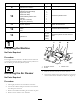
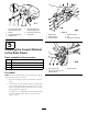
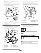
G003580
Figure2
1.Bolt
4.Cap
2.Aircleanerstrap5.Aircleanercanister
3.Machineframe
7.Coverthehoseorinstallaragintoitsothatnodirtor
debrisgetsintoitwhileinstallingthiskit.
8.Removetheoppositeboltholdingtheaircleanerstrap
tothemachineframe.
3
RemovingtheHydraulic
ReservoirandShrouds
NoPartsRequired
Procedure
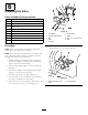
1.Drainthehydraulictank.Refertothemachine
Operator'sManual.
2.Raisetherearofthemachineoffthegroundandblock
uptherearofthemachine.Refertothemachine
Operator'sManualunderJackingtheMachine.
3.Removetheleftreartire.
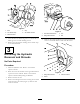
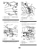
4.Removethe4ange-headscrewssecuringtheleft-hand
wheelshroudtotheframe(
Figure3).Removeand
retaintheshroud.
Figure3
1.Lefthandwheelshroud
3.Tire
2.Flange-headscrews4.Nut
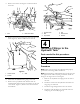
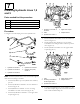
5.Removethe2ange-headscrewssecuringtheleftfront
screentotheframe.Removeandretainthescreen.
G003836
1
2
3
Figure4
1.Flange-headscrews
3.Leftfrontscreen
2.Frame
3