
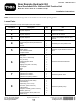
Installation Instructions
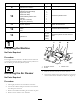
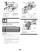
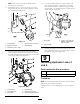

6.Removethe3boltssecuringtherearhitchshieldto
theframe.
Figure5
1.Bolt2.Rearhitchshield
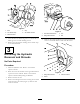
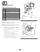
7.Removethe2screwssecuringthecentershroudtothe
frame(Figure6).Removeandretaintheshroud.
G003617
123
Figure6
1.Centershroud3.Seat
2.Screws
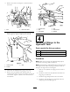
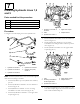
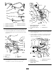
8.Disconnectthehydrauliclinesgoingtothetank.
9.Removethetophydraulictankbracketfromthe
machineframeandloosenthetwobracketsontheside
oftheframe.(
Figure7).Removethetankandretain
thehardware.
Figure7
1.Hydraulictank4.Nut
2.Bolt
5.Sidebracket
3.Topbracket6.Washer
4
InstallingFittingstothe
HydraulicTank
Partsneededforthisprocedure:
1
Small90degreeteewithbarb
1
Large90degreeelbow(threadedbothends)
1
Strainer
Procedure
Note:MakesureallO-ringsarelubricatedandproperly
positionedonallttingsbeforeinstallation.
Note:Installallttingsandhydrauliclineslooselyrstand
thentightenthemwheneverythingisinstalled.Installthe
ttingsattheanglesshowninthegures.
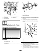
1.Removethe2hydraulictankplugsfromthesideof
thetank.
2.Installthestrainerintothehydraulictankwherethe
largeplugwasremoved.
3.Installthelarge90degreeelbowintothestrainer.
4.Installthesmall90degreeteewithbarbwherethe
smallplugwasremoved(
Figure8).
4