
Installation Instructions

6
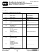
InstallingtheValve
Partsneededforthisprocedure:
1Valve
1Valveplate
2
Bolt,(1/4x1–3/4inches)
2
Nut,(1/4inch)
1
Small90degreeelbow
1
Teetting
2
Tappingbolt,(9/32x3/4inch)
1Teeadapter
1Relay
1
Cap
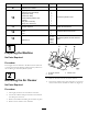
Procedure
Note:MakesureallO-ringsarelubricatedandproperly
positionedonallttingsbeforeinstallation.
Note:Installallttingsandhydrauliclineslooselyrstand
thentightenthemwheneverythingisinstalled.Installthe
ttingsattheanglesshowninthegures.
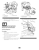
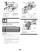
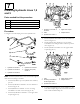
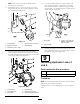
1.Installthettingsattheanglesshowninthegures.
Installtheteettingtothesideofthevalve.Referto
Figure11forthecorrectteetting.
2.Installasmall90degreeelbowtothetopofthevalve
(Figure11).
3.Installtheteeadaptertothe90degreeelbow .Refer
toFigure11forthecorrectteetting.
4.Installthecapontotheteeadapter(Figure11).
5.Installtherelaytothevalvebracketatthesametime
thevalveisinstalledtothevalvebracket.
6.Installthevalvetothevalvebracketwith2bolts(1/4x
1–3/4inches)and2nuts(1/4inch)(
Figure11).
G003576
6
5
4
3
2
1
9
7
8
Figure11
1.Teeadapter6.Valvebracket
2.Small90degreeelbow
7.Relay
3.Nut
8.Bolt,(1/4x1–3/4inches)
4.Valve
9.Cap
5.Teetting
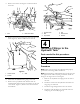
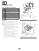
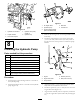
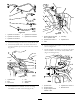
7.Installthevalvebrackettothemachineframewith2
tappingbolts(9/32x3/4inch)(Figure12).
12
G003577
Figure12
1.Tappingbolt(9/32x3/4
inch)
2.Valveassembly
6