
Installation Instructions
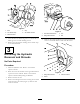
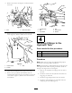
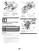
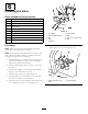
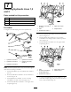
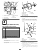
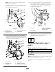
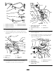

Figure16
1.Hydrauliclinenumber1
4.Hydraulicline(hose)
number5
2.Couplerbracket
5.Hydrauliccap
3.Lowermalecoupler
8
InstallingtheHydraulicPump
Partsneededforthisprocedure:
1Hydraulicpump
1
45degreetting(maleends)
1Hubassembly
1
Squarekey(1/4x1inch)
4
Setscrew,(5/16x3/4inch)
1Pumpbracket
2
Bolt(withLoctite
®
),(5/16x3/4inch)
2
Washer,(3/8inch)
1
Large90degreeelbow(withhosebarbedend)
Procedure
1.Installthelargesquare90degreeelbowtothesideof
thehydraulicpump.
2.Installthe45degreeelbowtothesideofthehydraulic
pump(
Figure17).
Figure17
1.45degreeelbow4.Maleend
2.Hydraulicpump5.Femaleend
3.Large90degreeelbow
(withhosebarbedend)
3.RemovetheexistingcoverovertheenginePTO(Power
TakeOff).
4.Installthepumpbrackettotheenginewith2bolts
(5/16x3/4inch)and2washers(3/8inch).Referto
Figure18forthecorrectpositiontoinstallthepump
bracket.
G003818
1
2
3
4
5
Figure18
1.Engine
4.Washer(3/8inch)
2.EnginePTOshaft5.Bolt(5/16x3/4inch)
3.Pumpbracket
5.ApplyNever-Seez
®
totheenginePTO(PowerTake
Off)shaftandthehydraulicmotorshaft.
6.Installthesquarekey(1/4x1inch)intotheslotinthe
enginePTOshaft(Figure19).
7.Alignthehubassemblywiththesquarekeyandinstall
itontotheenginePTO(PowerTakeOff)shaft(Figure
19).
8