
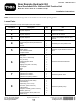
Installation Instructions
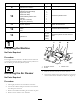

Note:Makesurethatthehubassemblyistotally
bottomedoutontheshaft.
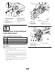
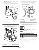
8.ApplyblueLoctite
®
tothe2setscrews(5/16x3/4
inch)andinstallthemintothehubassemblytosecure
ittothePTOshaft(Figure19).
G003610
1
2
3
4
5
Figure19
1.Pumpbracket
4.Setscrew(5/16x3/4inch)
2.EnginePTOshaft
5.Hubassembly
3.Squarekey,(1/4x1inch)
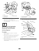
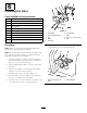
9.Installthepumpplatestudintothepumpbracket
whileinstallingthehydraulicpumpshaftintothehub
assembly.Thehydraulicpumpshaftwilltouchtheend
oftheenginePTOshaft(Figure20).
G003612G003612
1
2
3
1
2
3
4
5
4
5
6
Figure20
1.Pumpbracket4.Hubassembly
2.Pumpplatestud
5.Hydraulicpumpshaft
3.Pumpplate
6.Setscrew(5/16x3/4inch)
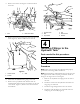
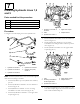
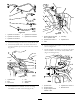
10.Thehubassemblyneedstobetotallyseatedonthe
shaft.Verifythatthereisagapbetweenthepump
plateandhubassembly.Ifthereisnogap,thenthe
hubassemblyisnotinstalledcorrectlyandneedstobe
seatedcorrectly(Figure21).
123
G003606
Figure21
1.Pumpplate3.0.040to0.122inchgap
betweenhubassembly
andpumpplate
2.Hubassembly
11.ApplyblueLoctite
®
tothe2setscrews(5/16x3/4
inch)andinstallthemintothehubassemblytosecure
thehydraulicpumpshaft(Figure20).
9
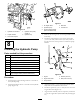
InstallingHydraulicLines3
and4
Partsneededforthisprocedure:
1Hydrauliclinenumber3
1Hydrauliclinenumber4
Procedure
Note:Installallhydrauliclineslooselyrstandthentighten
themwhenalleverythingisinstalled.
UseFigure22asakeyforidentifyingthecorrecthydraulic
lines.
9