
Installation Instructions


1
2004 by The Toro Company
8111 Lyndale Avenue South
Bloomington, MN 55420-1196
Contact us at www.Toro.com
All Rights Reserved
Printed in the USA
Front Blade Kit
Sand Pro
Model No. 08821—Serial No. 250000001 and Up
Form No. 3352–976
Installation Instructions
Loose Parts
Note: Use the chart below to identify parts used for assembly.
Description Qty. Use
Blade
Channel
Carriage bolts, 5/16 x 1 inch
1
1
4
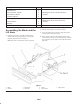
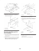
Assembling the blade and lift arms
Locknuts, 5/16 inch
Lift arm assembly (left)
Lift arm assembly (right)
Carriage bolts, 5/16 x 1 inch
Locknuts, 5/16 inch
Spacers
Cap screws, 3/8 x 3-3/4 inches
Locknuts, 3/8 inch
4
1
1
4
4
4
4
4
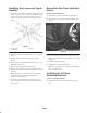
Mounting the lift arms to the blade and channel
assembly
Lower handle
Upper handle
Cap screws, 5/16 x 1-3/4 inches
Cap screws, 5/16 x 2-1/4 inches
Cap screws, 5/16 x 2-3/4 inches
Jam nuts, 5/16 inch
Washers, 1/2 inch
Spacers
1
1
2
2
2
2
8
4
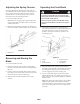
Mounting the handles to the handle plates
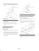
Pivot plates
Cap screws, 5/16 x 1-3/4 inches
Locknuts
2
4
4
Mounting to the foot rest (Sand Pro 14, 2000
and 3000)
Lift arm mounting bracket (left)
Lift arm mounting bracket (right)
Mounting blocks
Cap screws
1
1
2
4
Mounting lift arm mounting brackets to the
machine (Sand Pro 14, 2000 and 3000)
Lift arm mounting bracket (left)
Lift arm mounting bracket (right)
Cap screws, 1/2 x 1-1/4 inches
Flat washers, 1/2 inch
1
1
4
4
Mounting lift arm mounting brackets to the
machine (Sand Pro 5000 only)