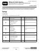
Form No. 3445-481 Rev A Midmount Toolbar System Sand Pro®/Infield Pro® 3040 and 5040 Traction Unit Model No. 08838—Serial No. 400000000 and Up Operator's Manual Important: Before installing the mid-mount toolbar system, you should obtain one of the toolbars available for use with the system. For more information, contact an authorized Toro distributor. Setup Loose Parts Use the chart below to verify that all parts have been shipped.
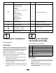
Procedure Description Use Qty. Lever assembly Bolt (5/16 x 2 inches) Locknut (5/16 inch) Pivot tab Toolbar link Carriage bolt (3/8 x 1-1/4 inches) Spacer Washer (1 inch) Locknut (3/8 inch) Pedal lever assembly Retaining ring Washer (7/8 inch) Bolt (5/16 x 1 inch) Eccentric bolt 1 1 3 1 1 1 1 1 1 1 2 1 1 1 Install the toolbar lift pedal. No parts required – Adjust the pivot spring tension and the adjustable rod assembly. No parts required – Adjust the toolbar transport height. 10 Shim (Part No.
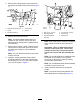
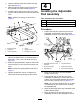
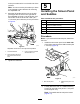
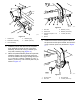
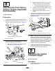
2. Remove the 4 flange-head screws that secure the right-hand wheel shroud to the frame (Figure 1). g003477 Figure 1 1. Right-hand wheel shroud 4. Screen panel 2. Nut (2) 5. Screws g025726 Figure 2 3. Bolt and washer (2) 3. Remove and retain the shroud. 1. Bolt (1/2 x 3-1/4 inch) 4. Thin locknuts (1/2 inch) 2. Mounting bracket 5. Footrest tube 3. Scarifier lift-handle assembly 6.
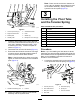
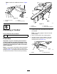
Note: There must be a minimum clearance of 3 mm (1/8 inch) between the hydraulic line and the lift handle assembly. Gently position the hydraulic line as required (Figure 2). 3 Installing the Pivot Tube and the Tension Spring Parts needed for this procedure: g019398 Figure 3 1 Pivot tube 1. Locknut (5/16 inch) (2) 5. Scarifier lift handle 1 Extension spring 2. Right rear frame tube 6. Knob 1 Spring rod 3. Detent plate 7. Washer (2) 2 Pivot tube bracket 4. Handle guide 8.
2. Loosely install the pivot tube bracket onto the right side (Figure 5). 3. Slide the right-hand side of the pivot tube into the right side pivot tube bracket (Figure 5). 4. Insert the spring rod into the hole in the spring bracket, and loosely secure it with a locknut (3/8 inch). 4 Installing the Adjustable Rod Assembly Note: Position the spring rod as shown in Parts needed for this procedure: Figure 6. 1 Adjustable rod assembly 1 Bolt (1/2 x 1-1/2 inches) 2 Locknut (1/2 inch) Procedure 1.
on the pivot tube until it is on the left side of the rod lever. 5 Note: You can move the pivot tube up or down in its brackets to gain clearance for mounting the adjustable rod. 6. Installing the Screen Panel and Saddles Move the lift handle until the hole in the ball joint aligns with the hole on the right-side of the adjustable rod lever on the pivot tube, and secure the rod to the lever with a bolt (1/2 x 1-1/2 inches) and a locknut (1/2 inch) as shown in Figure 8.
Note: Position the saddles as shown in Figure 10. g345308 Figure 10 1. Bolt (5/16 x 1 inch) 3. Lift arm 2. Saddle 4. Locknut (5/16 inch) g004101 Figure 11 6 1. Toolbar 2. Pivot bracket 1. Installing a Toolbar Position each end of the attachment tube onto the saddles. Note: The cutting edges of the tines should point forward. Parts needed for this procedure: 1 3. Fourth tooth 4. Tooth mounting hardware Toolbar (sold separately) Procedure 2. Move the lift handle to the middle position. 3.
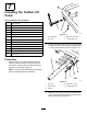
7 Installing the Toolbar Lift Pedal Parts needed for this procedure: 1 Lever assembly 1 Bolt (5/16 x 2 inches) 3 Locknut (5/16 inch) 1 Pivot tab 1 Toolbar link 1 Carriage bolt (3/8 x 1-1/4 inches) 1 Spacer 1. Lever assembly 3. Bolt (5/16 x 2 inches) 1 Washer (1 inch) 2. Pivot tube 4. Locknut (5/16 inch) 1 Locknut (3/8 inch) 1 Pedal lever assembly 2 Retaining ring 1 Washer (7/8 inch) 1 Bolt (5/16 x 1 inch) 1 Eccentric bolt g345309 Figure 13 2.
g004105 Figure 16 g345310 Figure 15 1. Toolbar link 4. Retaining ring 2. Pedal lever assembly 5. Washer (7/8 inch) Install the post on the other end of the pedal lever assembly through the top of the lever assembly, and secure it using a washer (7/8 inch) and a retaining ring (Figure 15). 5.
8 Adjusting the Pivot Spring Tension and the Adjustable Rod Assembly 3. No Parts Required B. Rotate the ball joint shown in Figure 19 to change the length of the rod as follows: • To increase the gap, shorten the rod. • To decrease the gap, lengthen the rod. C. Install the rod with the bolt and the locknut, and test the clearance again. D. Repeat this procedure until the gap is correct.
2. Note: If the teeth on one side of the toolbar contacts the ground before the other side, level the toolbar. Continue leveling by following the remainder of this procedure. Rotate the eccentric bolt either direction until the toolbar tines are parallel to the notch in the lift arm (Figure 17 and Figure 21). Important: The eccentric bolt will not rotate 5. 360 degrees. When it stops, do not attempt to force it further or you will damage it. Instead, rotate it back the other direction.
11 Reading and Storing the Documentation No Parts Required Procedure 1. Read the documentation. 2. Store the documentation in a safe place.
Operation • To lower the toolbar, move the lift handle to the left, lower it, and then slide it to the right into the desired detent position. • To raise the toolbar, move the lift handle to the left, raise it, and then slide it to the right into the desired detent position. • To raise and lock the toolbar into the transport position, move the lift handle to the highest position and press the toolbar lift pedal down.
Troubleshooting Problem Lifting the attachment requires excessive force. Possible Cause Corrective Action 1. The extension springs are too loose. 1. Tighten the nuts that secure the spring rods to tension the extension springs, and level the toolbar, if necessary. 2. The bell crank or handle assembly is too tight. 2. Loosen the 2 nuts that secure the bell crank and handle assembly to the scarifier mount assembly (refer to the Parts Catalog for parts illustration).
Notes:
The Toro Warranty Two-Year or 1,500 Hours Limited Warranty Parts Conditions and Products Covered The Toro Company warrants your Toro Commercial product (“Product”) to be free from defects in materials or workmanship for 2 years or 1,500 operational hours*, whichever occurs first. This warranty is applicable to all products with the exception of Aerators (refer to separate warranty statements for these products).