/ !2241% -!7)-4- 2!&%38 /03)-4- 0%1&/1-!.#% !.$ 3/ '!). +./6,%$'% /& 3(% 01/$4#3 )3 )2 %22%.3)!, 3(!3 8/4 /1 !.8 /3(%1 /0%1!3/1 /& 3(% -!#().% 1%!$ !.$ 4.$%123!.$ 3(% #/.3%.32 /& 3()2 -!.4!, "%&/1% 3(% %.').% )2 %5%1 23!13%$ !8 0!13)#4,!1 !33%.3)/. 3/ 3(% ()'(,)'(3%$ "8 3()2 28-"/, (% 2!&%38 !,%13 28-"/, -%!.2 /1 9 0%12/.!, 2!&%38 ).2314#3)/. !),41% 3/ #/-0,8 6)3( 3(% ).2314#3)/.
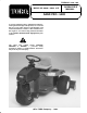
The SAND PRO 5020 was developed to provide an efficient, trouble free and economical method of sand trap maintenance. The latest concepts of engineering, design and safety have been incorporated into this machine, along with the highest quality parts and workmanship. Excellent service will be derived if proper operation and maintenance practices are followed.
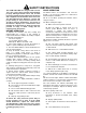
# # # Changing Engine Oil and Filter . . . . . . . . . . . . . 18 Servicing Engine Air Cleaner . . . . . . . . . . . . . . .
# ! +( 9$5 '(5,*1(' $1' 6(56(' 62 2))(4 5$)( 5(48,&( 9+(1 23(4$6(' $1' 0$,16$,1(' 3423(4/: /6+27*+ +$;$4' &21642/ $1' $&&,'(16 34(8(16,21 3$46,$//: $4( '(3(1'(16 7321 6+( '(5,*1 $1' &21),*74$6,21 2) 6+( 0$&+,1( 6+(5( )$&6245 $4( $/52 '(3(1'(16 7321 6+( $9$4(1(55 &21&(41 $1' 3423(4 64$,1,1* 2) 6+( 3(45211(/ ,182/8(' ,1 6+( 23(4$6,21 64$153246 0$,16(1$1&( $1' 5624$*( 2) 6+( 0$&+,1( 03423(4 75( 24 0$,16(1$1&( 2) 6+( 0$&+,1( &$1 4(57/6 ,1 ,1-74: 24 '($6+ 2 4('7&( 6+( 326(
!% ! " ! Whenever machine is left unattended, be sure engine is stopped, parking brake engaged, implement is lowered and key is removed from ignition. ! . Before servicing or making adjustments to the machine, stop the engine and pull the spark plug wire off spark plug to prevent accidental starting of the engine. Make sure all hydraulic line connectors are tight, and all hydraulic hoses and lines are in good condition before applying pressure to the system.
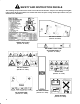
!# ! " ! !+( )0--06,/* 3$)(47 $/' ,/3425&4,0/ '(&$-3 $2( ,/34$--(' 0/ 4+( .$&+,/( ) $/7 %(&0.( '$.$*(' 02 ,--(*,%-( 2(1-$&( 4+(. (&$- 1$24 /5.%(23 $2( -,34(' %(-06 $/' ,/ 4+( 1$243 &$4$-0* 2'(2 2(1-$&(.(/43 )20.
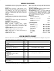
.-%(&41 3(.- Tricycle vehicle with welded steel frame construction. Rear engine placement. All wheels powered. -&(-$: Briggs & Stratton, V-twin cylinder, 4 cycle, OHV, air cooled, gas engine with cast iron sleeves. 18 hp @ 3600 rpm, 34.8 cu. in. (570 cc) displacement, 1.75 qt. oil capacity. Electronic ignition. Full pressure lubrication, oil filter. Engine and remote mounted air cleaners. 4&$ Hour meter. .-31.+2 Hand operated throttle, choke, lift lever and parking brake.
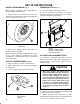
" ,* ! # ,* 15( Install the rear wheels to the machine while it is still on the pallet shipping blocks. Pivot seat upward and engage seat prop. Mount a wheel to each wheel motor and secure with lug nuts. Tighten lug nuts evenly and gradually in a crisscross manner to 45-55 ft-lb. Remove (2) wing nuts and washers securing top battery hold down to side battery hold downs. Remove top battery hold and remove battery.
When battery is charged, disconnect charger from electrical outlet and battery posts. Allow battery to sit for 5 to 10 minutes before proceeding to next step. Remove filler caps and slowly add electrolyte to each cell until level is up to fill line. Install filler caps. : . -.2 .4$0%(++ ! 22$06 +$"20.+62$ 5(++ .4$0%+.5 .-2. .2'$0 / 021 .% 2'$ , "'(-$ -# 1$4$0$ ".00.1(.- -# #$2$0(.0 2(.
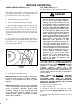
BEFORE OPERATING CHECK CRANKCASE OIL (Fig. 4) FILL FUEL TANK (Fig. 5) Fuel tank capacity is approximately 5.5 gallons. The engine is shipped with 1-3/4 quarts (w/ filter) of oil in the crankcase; however, level of oil must be checked before and after the engine is first started. 1. Position machine on a level surface. 2. Pivot seat upward and engage seat prop. 3. Pull out dipstick and wipe it with a clean rag. Insert dipstick into tube and make sure it is seated fully.
" If oil level is low, slowly fill with Mobil 424 or equivalent hydraulic oil until level is up to top of cone point on tank screen. " $ .,85* 8*0 7&2/ (&4 % # !%!" ., The hydraulic system is designed to operate on anti-wear hydraulic fluid. The machines reservoir is filled at the factory with approximately 3 gallons of Mobil 424 hydraulic fluid. -*(/ 0*9*0 3+ -;)5&80.( +08.) '*+35* *2,.2* .6 +.567 67&57*) &2) )&.0; 7-*5*&+7*5 5384 ;)5&80.
KNOW YOUR CONTROLS Traction and Stopping Pedal (Fig. 8 - 9) - Traction pedal has three functions: one, to make the machine move forward, two, to move it backward and three, to stop machine. Using the heel and toe of the right foot, depress top of pedal to move forward and bottom of pedal to move backward or to assist in stopping when moving forward. Allowing pedal to move to neutral position will stop machine. For operator comfort, do not rest heel of foot on reverse when operating forward (Fig. 9).
*/, . , (Fig. 10) - (Located under seat) Indicates the total hours of machine operation. The Hour Meter starts to function whenever the key switch is rotated to ON" position. . %/-.$)" 0 , (FIg.12) - Lever on left side of seat allows seat to be adjusted fore and aft for operator comfort. $!. 0 , (Fig.10) -To raise the implement, pull the lever backward; to lower implement, push the lever forward.
! Check interlock operation in a wide open area free of debris and bystanders. Stop engine. Remove foot from traction pedal, make sure pedal is in neutral position and engage parking brake. Sit on the seat. Depress traction pedal in forward and reverse directions, while trying to start the engine. If engine cranks there may be a malfunction in the interlock system. Repair immediately. If engine does not crank, system is operating correctly.
To maintain somewhat constant engine speed, depress traction pedal slowly. This allows the engine to keep up with ground speed of the vehicle. By contrast, pushing down quickly on the traction pedal will reduce engine rpm and, as a result, there will not be enough torque-power-to move the vehicle. Therefore, to transfer maximum power to the wheels, move throttle to FAST and slightly depress traction pedal.
$& ' &* # $& " # )'(" #(' ($ ( " # '($% # # %)!! + & ' $ '% & %!) ' # & "$* , &$" ( '+ ( The Sand Pro has (5) grease fittings that must be lubricated regularly with No. 2 General Purpose Lithium Base Grease. Lubricate front wheel bearing and Traction Control Linkage after every 50 hours of operation. Lubricate steering shaft every 100 hours. The bearings and bushings that must be lubricated are: front wheel bearing (Fig.
(duplicate this page for routine use) Daily Maintenance Check For Week Of ___________ Maintenance C Check Item b MON n Safety Interlock Operation n Steering Operation n Engine Oil Level n Remote Air Filter Dust Cup TUES WED THURS FRI SAT SUN Clean Engine Cooling Fins n Unusual Engine Noises n Unusual Operating Noises n Hydraulic System Oil Level n Hydraulic Hoses for Damage n Fluid Leaks n Fuel Level n Tire Pressure n Instrument Op
&$ sure carburetor breather hose is routed out through engine vents. Change oil initially after the first 8 hours of operation, thereafter change oil every 50 hours and filter every 100 hours. Park the machine on a level surface and turn the engine off. Remove drain plug and let oil flow into drain pan. When oil stops, install drain plug. Remove oil filter. Apply a light coat of clean oil to the new filter gasket.
! Gently slide filter out of air cleaner body to reduce the amount of dust dislodged. Avoid knocking filter against air cleaner body. Inspect filter and discard if damaged. Do not wash or reuse a damaged filter. Service the air cleaner filter every 400 hours (more frequently in extreme dusty or dirty conditions). Do not over service air filter. #$3*+/) (4*0' A. Prepare a solution of filter cleaner and water and soak filter element about 15 minutes.
" Check condition of side electrode, center electrode, and center electrode insulator to assure there is no damage. I " " )7')1+* ,5:2+* */79= 57 59.+7
" $ # !$!" -+ Whenever a hydraulic component is repaired or replaced the hydraulic oil filter should be changed and hydraulic system charged. " " %/) 685) ,;(5%80-' 5)6)593-5 -6 *-00)( :-7, 3-0 %7 %00 7-1)6 :,)2 ',%5+-2+ ,;(5%80-' 6;67)1 Park the machine on a level surface and turn the engine off. Remove (3) screws securing side panel to right side of machine and remove panel.
Tighten locknut securing adjustment. Stop the engine. Remove jack stands and lower the machine to the shop floor. Test drive the machine to make sure it does not creep. " +) The pedal must be adjusted for forward if jam nuts on control rod are loosened or if pedal is removed. Park the machine on a level surface and turn the engine off. +)63' 6'. +.5'3 14' .
-0"4 03*4*0/ *( The lift lever detent plate can be adjusted if the attachment does not float properly (follow ground contour) during opertion. Park the machine on a level surface, turn engine off, set parking brake and block wheels. Loosen (2) capscrews securing lift lever detent plate to fender and frame. Thru access hole, in front fender, insert a 3/16" hex key into jacking screw on lift lever detent plate.
If the machine will be stored for more than 30 days, remove the battery and charge it fully. Either store it on a shelf or on the machine. Leave the cables disconnected if stored on the machine. Store the battery in a cool atmosphere to avoid quick deterioration of the charge in the battery. To prevent battery from freezing, make sure it is fully charged. The specific gravity of a fully charged battery is 1.250.
FRAME GND BLUE GREY (+) SOLENOID DETAIL WIRE HARNESS BATTERY (-) STARTER GREEN FRONT OF TRACTOR TO STARTER TO BATTERY REG.
OIL COOLER P1 P2 FILTER HYDROSTAT R2 R1 LIFT CYLINDER LIFT VALVE B A FWD REV M1 B RH WHEEL MOTOR WITH BLEED OFF FOR OIL COOLING IN FORWARD DISPLACEMENT, FLOW RATE, AND PRESSURE CHART DISPLACEMENT PRESSURE *FLOW RATE LBS/IN BARS LPM IN /REV CM /REV GPM .915 15 12.48 47.2 .33 5.41 4.5 17 8.6 140.93 8.6 140.93 17.1 280.22 700 48.3 90 6.
! & " ! !% ! ! !% #' $ !% ! ! #" &# Check Battery Fluid Level Check Battery Cable Connections { Change Engine Oil Lube Front Wheel Bearing Lube Traction Control Linkage !% ! ! !% #' #' Every 25hrs Every 100hrs Every 400hrs Every 800hrs Replace Engine Oil Filter Inspect Remote Air Filter Element Inspect Engine Air Filter Element Lube Steering Shaft Grease Fitting Check Steering Chain Adjustment { Torque Wheel Lug Nuts Change Hydraulic Oil {
The Toro Commercial Products Two Year Limited Warranty The Toro Company warrants your 1996 or newer Toro Commercial Product (Product") purchased after January 1, 1997, to be free from defects in materials or workmanship for the period of time listed below. Where a warrantable condition exists, Toro will repair the Product at no cost to you including diagnosis, labor, parts, and transportation. This warranty begins on the date the Product is delivered to the original retail purchaser.