
Service Bulletin
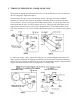


While holding the upper and lower crankshafts in alignment with the timing bar, install the
Drive Gear into the Gear Case (View C).
NOTE: If the external teeth of the Drive Gear will not align with the Idler Gears, remove
Timing Bar (82-3200) and the Drive Gear, then rotate the upper crankshaft 1/2 gear tooth
toward the rear of the aerator to align the teeth. Reinstall the Drive Gear (View C). Be careful
not to move the upper crankshaft position any more than 1/2 tooth to achieve proper alignment.
When the bearings have been installed on the Drive Gear, it no longer can be removed without
first removing the Idler Gears. If both bearings are installed on the Drive Gear and a timing
adjustment is necessary, remove the Upper Crankshaft Assembly from one side of the Gear
Case, move the gear one tooth in the direction noted in View C, and reinstall in the same
location. Moving the Upper Crankshaft Assembly is easier/faster than removing the Drive Gear
and also provides a more finite timing adjustment than the Drive Gear.
IMPORTANT: Do Not achieve alignment by rotating upper crankshaft towards the front of the
Aerator. For optimum hole quality, alignment must be accomplished by rotating the upper
crank toward the rear of the machine as indicated by the arrow in View C.
II. SYNCHRONIZING GEAR CASES TOGETHER
The purpose for timing the three Gear Cases, is to ensure the Aerator operates with the lowest
amount of vibration, and to minimize the amount of reaction force the unit must absorb when
the tines engage the soil.
IMPORTANT: The tine arms are numbered 1 to 6 from the left to right, as viewed from the
rear of the unit.
The next step is to perform a final orientation of the Corer Gear Cases. This step must be
performed to align the Drive Line Assembly with Gear Case Drive Gears.
Each of the three Corer Gear Cases must be connected to the other in a "Proper-Phase"
condition so that only one set of tines will enter the turf at a time. Rotate the "Number one" tine
block to its lowest position as a starting point. When viewed from the left side of the Coring
Head, the stamped numbers "2", "3", and "1" should be visible at the top of the first, third, and
fifth upper crank respectively (View D). While maintaining the relationship between the three
Gear Cases, install the Drive Line Spline Shafts to the couplings. If you are unable to achieve
spline alignment, re-index the spline using the bolt hole pattern in the coupling flanges as
required.