
Operator's Manual

26
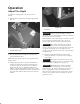
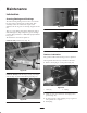
B. Rotate hex on top of idler tube until the bottom of
the rubber boot is between the two grooves in the
guide tube. At this position the spring will be
compressed to a length of 3 inches (76 mm).
C. Tighten jam nut.
1
2
3
4
Figure 31
1. Idler spring boot
2. Jam nut
3. Idler tube
4. Bottom guide tube groove
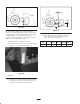
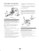
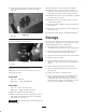
Replacing Belts
1. Loosen jam nut securing idler tube to tensioner arm
(Fig. 32).
2. Rotate hex on top of idler arm until all spring tension
is removed (Fig. 32).
Springs are under tension, use caution when
adjusting or removing.
Caution
3. Remove hair pin cotter and idler pin securing top of
spring assembly to frame (Fig. 32).
2
4
3
6
5
1
7
Figure 32
1. Idler spring boot
2. Jam nut
3. Adjusting nut
4. Idler pin & hairpin cotter
5. Idler pulley
6. Hairpin cotter & idler shaft
7. Tine arm assembly
4. Remove hair pin cotter securing idler pulley assembly
to idler shaft (Fig. 32). Remove idler assembly from
shaft.
5. Remove screw, lock washer and flat washer securing
top of tine arm to pulley (Fig. 32).
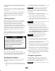
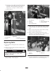
6. Remove fasteners securing bottom of tine arm or
rotalink arm to bottom links (Fig. 33). Align tine arm
with slot in frame and slide off crank pin.
1
2
3
Figure 33
1. Tine arm
2. Bottom link
3. Rotalink arm
7. To ensure components are re–installed correctly, mark
location of end cover on aerator frame (Fig. 34)