
Operator's Manual


9
Setup
Note: Determine the left and right sides of the machine from the normal operating position.
Loose Parts Chart
Note: Use this chart as a checklist to ensure all parts necessary for assembly have been shipped. If any of these parts are
missing, total setup cannot be completed.
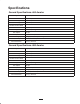
Description Qty. Use
PTO drive shaft 1 Transfers power from tractor to aerator
Rear castor/safety shield 1 Support aerator for maintenance/storage
Side guards 2 Keeps hands and feet away from tines
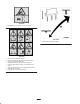
Keys 2 For hood latch on TE models
Operator’s Manual 2 Read before operating machine
Parts Catalog 1 Service part identification
Tractor Requirements
• 24 horsepower—660
• 32 horsepower—880
• Correct tire pressure
• Category one 3 point hitch, rated to lift at least a
1400 lb. (637 Kg) implement–660
• Category one 3 point hitch, rated to lift at least a
1700 lb. (771 Kg) implement–880
• 540 rpm tractor PTO
• Adequate front-end weight (ballast)
Ballast Requirements
To help prevent bodily injury and provide added
stability, make sure front of the tractor is
equipped with proper ballast. Refer to tractor
operator’s manual for ballast requirements.
Caution
• Refer to Tractor Operator’s Manual for ballast
requirements.
Connect Lower Link Arms
1. Aerator must be positioned on a flat, level surface for
installation.
2. Back tractor squarely up to aerator until lower link
arms are aligned with hitch pins.
3. Make sure PTO is disengaged.
4. Engage parking brake, STOP engine and remove key
from ignition. Wait for engine and all moving parts to
STOP before leaving operator’s seat on tractor.
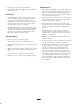
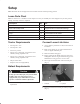
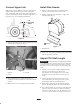
5. Insert right and left lower link arms onto hitch pins
(Fig. 2).
1
2
Figure 2
1. Lower link 2. Lynch pin
6. Secure lower link arms to hitch pins with lynch pins
(Fig. 2).