Form No. 3437-560 Rev D ProCore® 864 and 1298 Aerators Model No. 09715—Serial No. 403410001 and Up Model No. 09716—Serial No. 403410001 and Up Register at www.Toro.com.
This product complies with all relevant European directives; for details, please see the separate product specific Declaration of Conformity (DOC) sheet. WARNING CALIFORNIA Proposition 65 Warning Use of this product may cause exposure to chemicals known to the State of California to cause cancer, birth defects, or other reproductive harm. g262223 Figure 1 Model 09716 Introduction 1.
After Operation Safety ...................................... 27 Transporting the Machine ................................. 27 Cleaning the Machine after Use ........................ 27 Maintenance ........................................................... 28 Recommended Maintenance Schedule(s) ........... 28 Maintenance Safety.......................................... 28 Jacking the Machine ......................................... 29 Greasing the Bearings and Bushings ................
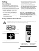
Safety • Do not operate the machine without all guards General Safety • This product is capable of amputating hands and feet and of throwing objects. Always follow all safety instructions to avoid serious personal injury. • • Using this product for purposes other than its intended use could prove dangerous to you and bystanders. • Read and understand the contents of this Operator’s Manual before using the machine. and other safety protective devices in place and functioning properly on the machine.
decal110-4668 110-4668 1. Entanglement hazard, shaft—stay away from moving parts. 2. PTO speed and input direction. 3. Use clip to secure lash cable when not in use. Use lash cable to support the power take-off when the machine is disconnected from tractor. decal110-4678 110-4678 1. Coring depth decal110-4667 110-4667 1. Spring length 2. Stored energy hazard—read the Operator's Manual. 3. Entanglement hazard, belt—stay away from moving parts. decal110-4670 110-4670 1.
decal92-1581 92–1581 decal92-1582 92–1582 decal110-4677 110-4677 1. Turn clockwise to decrease aeration depth. 2. Turn counterclockwise to increase aeration depth. decal110-4664 110-4664 1. Read the Operator's Manual. 2. Wrench size 3. Bolt size 4. Torque decal106-8856 106-8856 1. Read the Operator's Manual.
decal133-8061 133-8061 decal138-9038 138-9038 1. Entanglement hazard—read the Operator’s Manual; stay away from moving parts; keep all guards and shields in place.
Setup Loose Parts Use the chart below to verify that all parts have been shipped. Procedure 1 2 3 4 5 6 7 8 9 10 11 12 Description Qty. Use No parts required – Inspect the machine. Lynch pin 2 Connect the lower link arms. Link pin Lynch pin Bolt (1/2 x 3 inches) Nut (1/2 inch) Short driveshaft, Part No. 115-2839 (may be needed; sold separately) 1 1 1 1 No parts required – Adjust the sway links. No parts required – Level the machine side-to-side.
1 Inspecting the Machine No Parts Required Procedure ProCore 864 Use the following list as a reference: • Use a 30 PTO horsepower minimum when aerating in light to normal soil conditions (sandy to sandy/loam soils with average compaction). • Use a 35 PTO horsepower minimum when aerating in normal to heavy soil conditions (heavy loam, clay, and rocky soils with above average compaction).
3. Back the traction unit squarely up to the machine until the lower link arms are aligned with the hitch pins. 4. Engage the parking brake, shut off the engine, and remove the key from the ignition. Wait for the engine and all moving parts to stop before leaving the operator's seat. 3 Connecting the Upper Link Parts needed for this procedure: Note: For maximum ground clearance, install the hitch pins in the lower mounting holes of the hitch plate for the machine (Figure 5).
2. Grease the threaded steel upper link tubes. 3. Rotate the upper link to tighten the link. Adjust it until the frame at the front of the machine is vertical (Figure 8). 4. Tighten the locknut to secure the upper link into position. the lower trailing arms (Figure 9). Record your measurement here: Important: Contact your authorized Toro distributor if you need any assistance when performing this measurement and if you need to order an optional shorter PTO driveshaft assembly. 4 3.
g007328 Figure 12 g007295 Figure 10 ProCore 864 1. PTO output shaft (traction unit) 3. PTO driveshaft 2. PTO shaft coupler 1. Lower PTO shield 2. Clip nut 2. 3. Screw Assemble the PTO driveshaft to the gearbox input shaft of the machine (Figure 11) with a bolt (1/2 x 3.00 inches) and a nut (1/2 inch). 4. Slide the PTO driveshaft forward as far as the PTO output shaft allows. 5. Pull back on the locking collar of the PTO shaft coupler to secure the PTO driveshaft.
5 6 Adjusting the Sway Links Leveling the Machine Side-to-Side No Parts Required No Parts Required Procedure Procedure • The ProCore 864 is designed to be offset from the traction unit center line. The gearbox input shaft is offset 40 mm (1.57 inches) to the left of center and the machine is offset 145 mm (5.70 inches) to the right of the center line. Adjust the sway links as needed. 1. Park the traction unit and the machine on a level, firm surface. 2.
9 Installing the Turf Guards Parts needed for this procedure: – Procedure g007330 Figure 16 1. Roller scraper A wide selection of turf guards is available for the machine. Use the appropriate turf guards for the selected tine heads. 2. Nut 2. Slide the roller scraper in or out until the required position is attained, and tighten the fasteners. 3. On the ProCore 864 only, you can adjust the stop bolt on the center support to attain the proper gap. Turf guards (not included) 1.
10 11 Securing the Hood Latches (CE only) Applying the Entanglement Decal Parts needed for this procedure: CE Mowers 1 CE Compliance Kit, Part No. 110-4693 (not included) Parts needed for this procedure: 4 Procedure Note: The CE Completion Kit, Part No. 110-4693 is Procedure required to complete this step. 1. CE entanglement decal Important: This procedure is required for all CE countries and anywhere English is not commonly spoken.
4. Place the CE entanglement decal over the existing entanglement decal (Figure 19). 12 Removing the Storage Stands Parts needed for this procedure: 4 Lynch pin (ProCore 864) 8 Lynch pin (ProCore 1298) Procedure 1. Raise the machine 7.6 to 15.2 cm (3 to 6 inches) off the ground. 2. Remove the nuts and the lock washers securing the storage stands to the machine (Figure 20). g007303 Figure 20 1. Storage stand 3. Nut 2. Lock washer 3. Remove the storage stands. 4.
Specifications Product Overview Note: Specifications and design are subject to Controls change without notice. ProCore 864 Aerator Depth Adjuster Rotate the depth adjuster input shaft clockwise to reduce the aeration depth or counterclockwise to increase the aeration depth (Figure 21). Working Width 163 cm (64 inches) Overall Width 170 cm (67 inches) Overall Length 89 cm (35 inches) Overall Height 98 cm (38.
ProCore 864 Tine Configuration Table 1 of 3 Tine Kit Description Needle Tine Quad Tine (2x5) Quad Tine (1x6) Model No. 09739 09736 09737 Kit Qty. 4 4 4 Tines Required 40 80 48 Lateral Spacing 40 mm (1.6 inches) 40 mm (1.6 inches) 33 mm (1.3 inches) Mount 5 mm and 8 mm 10 mm (3/8 inch) diameter 10 mm (3/8 inch) diameter Turf Guard Part No. 120-1047 120–1061 120-1062 120-1047 120-1061 120-1062 120-1050 120-1063 120-1064 Required Qty.
ProCore 864 Tine Configuration Table 3 of 3 Tine Kit Description Quick Change (3-Tine) Quick Change (4-Tine) Model No. 09711 09719 Kit Qty. 4 4 Tines Required 24 32 Lateral Spacing 66 mm (2.6 inches) 51 mm (2.0 inches) Mount Not Applicable Not Applicable Sleeve Description 19 mm (3/4 inch) 122 mm (7/8 inch) 19 mm (3/4 inch) 22 mm (7/8 inch) Part No. 108-6837 108-6838 108-6837 108-6838 Required Qty. 24 24 32 32 Tool Kit Part No. (1 required) 114-0890-01 Turf Guard Part No.
ProCore 1298 Tine Configuration Table 2 of 2 Tine Kit Description 4-Tine 3-Tine HD Quick Change (3-Tine) Quick Change (4-Tine) Model No. 09796 09797 09711 09719 Kit Qty. 6 6 6 6 Tines Required 48 36 36 48 Lateral Spacing 51 mm (2.0 inches) 66 mm (2.6 inches) 66 mm (2.6 inches) 51 mm (2.0 inches) Mount 19 mm (3/4 inch) diameter 22 mm (7/8 inch) diameter Not Applicable Not Applicable Sleeve Description Not Applicable Part No. Not Applicable Required Qty.
Adjusting the Aeration Depth Operation Note: Determine the left and right sides of the machine from the normal operating position. Important: Adjust the aeration depth only when the traction unit is parked, the parking brake is engaged, the PTO is disengaged, and the engine is shut off. Before Operation 1. Before Operation Safety Lay the desired tine onto the depth decal while aligning the tine tip with the desired aeration depth as shown in Figure 22.
Understanding the Principles of Operation The 3-point hitch linkage of the traction unit lifts the machine for transport and lowers it for operation. Power from the traction unit power take-off (PTO) is transmitted through driveshafts, a gearbox, and drive belts to a number of crankshafts, which drive the tine holding arms into the turf surface. As the traction unit travels forward with the PTO engaged and the machine lowered, a series of holes are created in the turf.
• Wear appropriate clothing, including eye the area being aerated, mark these locations to ensure that these items are not damaged during operation. • Operate the traction unit using the recommended gear settings and PTO drive speeds and become thoroughly familiar with the traction unit handling with the attached machine. • Practice stopping and starting, raising the machine, and lowering the machine, disengaging the PTO drive, and aligning the machine with previous passes.
Important: Never operate the traction unit operation. Operating the machine on any slope requires extra caution. PTO faster than 540 rpm or you may damage to the machine. • Evaluate the site conditions to determine if the slope is safe for machine operation, including surveying the site. Always use common sense and good judgment when performing this survey. Note: Make sure that the roller is on the ground. 5.
Adjusting the Hole Spacing The forward hole spacing is determined by the traction unit gear ratio (or the hydrostatic traction pedal). Changing the engine speed does not change the forward hole spacing. The lateral hole spacing is determined by the number of tines in the tine heads. Hole spacing Ground speed mm (inch) km/h (mph) 25 (1) 0.6 (0.4) 0.6 (0.4) 0.6 (0.4) 0.6 (0.4) 0.6 (0.4) 0.6 (0.4) 0.6 (0.4) 0.6 (0.4) 0.8 (0.5) 0.8 (0.5) 0.8 (0.5) 0.8 (0.5) 0.8 (0.5) 32 (1.25) 0.8 (0.5) 0.
Adjusting the Rotalink Assembly Aerating Hard Ground If the ground is too firm to obtain the desired coring depth, the coring head can get into a “bouncing” rhythm. This is due to the tines attempting to penetrate the hard pan. This condition can be corrected by attempting one or more of the following: • Best results are obtained after a rain or when turf has been watered the previous day. • Reduce the number of tines per stomper arm.
Operating Tips • Always clear the area of all damaged machine parts, such as broken tines, etc., to prevent them from being picked up and thrown by mowers or other turf maintenance equipment. WARNING Adjusting or repairing the machine while the traction unit is running may result in an accident and severe injury or death • Before leaving the operator’s seat, disengaging the PTO drive, engaging the parking brake, shutting off the engine, and remove the key.
Maintenance Recommended Maintenance Schedule(s) Maintenance Service Interval Maintenance Procedure After the first 8 hours • Change the gearbox lubrication. • Check the torque of the coring head fasteners. Before each use or daily • Check the belt tension. • Check the belt tension. Every 50 hours • Grease the bearings and bushings. • Inspect the bearings. Every 100 hours • Check the gearbox lubrication. Every 250 hours • Change the gearbox lubrication.
Jacking the Machine The lubrication points are: PTO driveshaft (3) (Figure 27) CAUTION If the machine is not properly supported by blocks or jack stands, the machine may move or fall, which may result in personal injury. • Ensure that the machine is parked on a solid, level surface such as a concrete floor. Always chock the traction unit tires. • Prior to raising the machine, remove any attachments that may interfere with the safe and proper raising of the machine.
Important: Bearings rarely fail from defects in materials or workmanship. The most common reason for failure is moisture and contamination working its way past the protective seals. Bearings that are greased rely upon regular maintenance to purge harmful debris from the bearing area. Sealed bearings rely on an initial fill of special grease and a robust integral seal to keep contaminants and moisture out of the rolling elements. The sealed bearings require no lubrication or short term maintenance.
Changing the Gearbox Lubrication Inspecting the Belts Service Interval: After the first 8 hours The drive belt(s) on the machine are durable. However, the normal exposure to UV radiation, ozone or incidental exposure to chemicals can deteriorate the rubber compounding over time and lead to premature wear or material loss (i.e. chunking). Service Interval: Yearly Every 250 hours The gearbox is filled with 80W-90 gear oil or equivalent.
Replacing the Drive Belt Note: You do not need to remove the outside stomper arm to replace the drive belt. Removing the Belt 1. Remove the rear coring head cover (Figure 35). g007316 Figure 33 1. Rear coring head cover 2. Pulley shield B. Remove the pulley shield mounting bolts and remove the shield (Figure 33). C. Loosen the locknut securing the spring retainer (Figure 34). g007316 Figure 35 1. Rear coring head cover 2. Pulley shield 2.
Installing the Belt 1. Route the new drive belt around the lower end of the #1 stomper arm and up through the coring head frame. 2. Position the drive belt onto the crank pulley, under the idler assembly and over the drive pulley. 3. Raise the rotalink damper for the #1 stomper arm to coring head frame. Ensure that the damper spacers are installed in the same position as in removal. 4. Secure the rotalink damper to the coring head with the 2 washers and locknuts previously removed. 5.
Adjusting the Side Shield Coring Head Timing The coring head side shields should be adjusted so that the bottom rides between 25 to 38 mm (1 to 1-1/2 inches) from the turf while aerating. The unitized coring head design of the machine provides industry-leading smooth operation while taking out the guesswork of timing. 1. Loosen the bolts and nuts securing the side shield to frame (Figure 39).
g007323 Figure 42 g007302 Figure 43 1. Lynch pins Removing the Machine from the Traction Unit Note: You can store the machine on the original shipping pallet. Important: Refer to the PTO driveshaft owner’s manual for additional operating and safety information. 1. 2. 2. Storage stand Park the traction unit and machine on a level surface, disengage the PTO, engage the parking brake, shut off the engine, remove the key, and wait for all moving parts to stop before leaving the operator's seat. 3.
Storage Storage Safety • Before adjusting, cleaning, storing, or repairing the machine, park the it on a level surface; engage the parking brake of the traction unit; shut off the engine; remove the key; and wait for all movement to stop before leaving the traction unit. • Store the machine on the storage stands g007307 positioned on a firm, level surface so that it does not sink or tip over. Figure 44 1. PTO tether • Store the machine away from areas of human 10. activity.
Notes:
EEA/UK Privacy Notice Toro’s Use of Your Personal Information The Toro Company (“Toro”) respects your privacy. When you purchase our products, we may collect certain personal information about you, either directly from you or through your local Toro company or dealer.
California Proposition 65 Warning Information What is this warning? You may see a product for sale that has a warning label like the following: WARNING: Cancer and Reproductive Harm—www.p65Warnings.ca.gov. What is Prop 65? Prop 65 applies to any company operating in California, selling products in California, or manufacturing products that may be sold in or brought into California.
The Toro Warranty A two-Year Limited Warranty Conditions and Products Covered The Toro Company and its affiliate, Toro Warranty Company, pursuant to an agreement between them, jointly warrant your Toro Hydroject or ProCore Aerator (“Product”) to be free from defects in materials or workmanship for two years or 500 operational hours*, whichever occurs first. This warranty is applicable to all products (refer to separate warranty statements for these products).