FORM NO. 3318–767 Rev. B HydroJect Injection System for HydroJect Aerators Model No. 09830 Operator’s Manual IMPORTANT: Read this manual carefully. It contains information about your safety and the safety of others. Also become familiar with the controls and their proper use before you operate the product.
Introduction We want you to be completely satisfied with your new product, so feel free to contact your local Authorized TORO Distributor for help with service, genuine replacement parts, or other information you may require. The warning system in this manual identifies potential hazards and has special safety messages that help you and others avoid personal injury, even death. DANGER, WARNING and CAUTION are signal words used to identify the level of hazard.
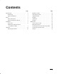
Contents Specifications . . . . . . . . . . . . . . . . . . . . . . . . . . . Productivity . . . . . . . . . . . . . . . . . . . . . . . . Approved Additives . . . . . . . . . . . . . . . . . . Safety . . . . . . . . . . . . . . . . . . . . . . . . . . . . . . . . . Safety Instructions . . . . . . . . . . . . . . . . . . . Safety and Instruction Decals . . . . . . . . . . Installation . . . . . . . . . . . . . . . . . . . . . . . . . . . . . Loose Parts . . . . . . . . . . . . . . . . . . . . . . . . .
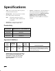
Specifications • Tank – The six-quart tank is made of nylon for excellent chemical resistance. • Mixing Ratios – The mixing ratios are variable from 1:100 (1.0%) to 1:500 (0.2%). Note: • • The decal on the injector is just a starting point. Further calibration may be required. Injector – The HydroJect Injection System is a water-driven liquid injector designed to inject proportionate amounts of completely dissolved additives that are recommended and approved.
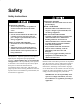
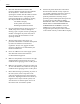
Safety Safety Instructions POTENTIAL HAZARD • Incorrect injection ratios can produce an unsafe concentration level in the outlet water. WHAT CAN HAPPEN • Unsafe concentration levels in outlet water caused by incorrect injection ratios can pose a danger to personal health, and can damage equipment. HOW TO AVOID THE HAZARD • Determine the correct solution injection ratios. • Adjust the injector to obtain the desired solution concentrations in the outlet water.
Safety 1. Read and understand the contents of this Operator’s Manual, and the Operator’s Manual for the HydroJect 3000 Aerator before operating the machine. Become familiar with all controls and know how to stop quickly. Free replacement manuals are available by sending the complete Model and Serial Number to: The TORO Company 8111 Lyndale Avenue South Bloomington, Minnesota 55420 2. Keep all shields and safety devices in place.
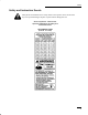
Safety Safety and Instruction Decals Safety decals and instructions are easily visible to the operator and are located near any area of potential danger. Replace any decal that is damaged or lost.
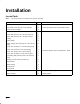
Installation Loose Parts Note: 6 Use the chart below to identify parts used for assembly. DESCRIPTION QTY. USE Locknut, 3/8”-16 3 Hex Head Screw, 3/8”-16 x 1-1/2” (38 mm) 3 Hole Location Template 1 Hose Clamp, 1/4”–5/8” (6–16 mm) 4 Hose, 3/8” (9.5 mm) I.D. x 68” (173 cm) long 1 Hose, 3/8” (9.5 mm) I.D. x 10” (25 cm) long 1 Fitting 1 Hose Clamp 6 Nylon Tubing, 3/16” (4.8 mm) I.D. x 30” (76 cm) long 1 Hose, 3/4” (19 mm) I.D. x 15-1/2” (39 cm) long 1 Hose, 1/4” (6 mm) I.D.
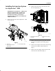
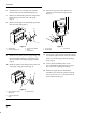
Installation Installing the Injection System to a HydroJect 3000 2. Remove the hose between the water filter and the water pump (Fig. 2). IMPORTANT: The HydroJect 3000 Aerator MUST be equipped with a regulator and pre-filter. If not, you must purchase and install these kits before you install the Injection System. (Contact your Authorized TORO Distributor.) 1. Remove the fuel tank from the HydroJect 3000 Aerator (Fig. 1). 1 1 2 Figure 2 1. Hose (between water filter and pump) 2.
Installation 6. Disconnect the valve assembly hose and tube retainer from the brass barbed fitting (Fig 3). 7. Remove the barbed fitting from the straight brass barbed fitting on the inlet side of the pump (Fig 3). 8. Remove the straight brass barbed fitting from the inlet side of the pump (Fig 3). 11. Install a O–ring seals, elbow fittings and interlock pins to bottom of liquid injector (Fig. 5). 2 1 1 2 3 4 3 Figure 5 Figure 3 1. Barbed Fitting 2. Valve Assembly Hose 9. 3.
Installation 1 2 3 90 80 70 60 50 40 30 20 10 1 4 2 m-2656 Figure 6 1. 3/8” Locknut (3) 2. 13/32” (10.5 mm) Diameter Hole (3) 3. Support Bracket 4. 3/8”-16 x 1-1/2” (38 mm) Hex Head Bolt (3) 15. Remove the old pressure gauge hose from the pressure gauge (Fig. 7). Figure 8 1. Plastic Pressure Gauge Fitting (new) 2. Pressure Gauge Hose (new) 17. Install new blue 3/4” (19 mm) hose from the filter to the inlet side of the liquid injector. Cut the hose to length as required (Fig. 9).
Installation 18. Install new blue 3/4” (19 mm) hose from the liquid injector outlet to the inlet side of the water pump. Cut the hose to length as required (Fig. 9). 19. Reconnect the valve assembly hose and tube retainer to the barbed fitting on the inlet side of the pump (Fig. 10). 1 1 2 2 3 3 4 Figure 10 1. Barbed Fitting 2. Tube Retainer 4 5 3 Figure 9 1. Water Pump 2. Filter 3. Blue 3/4” (19 mm) Hose (from Injector outlet to Pump inlet) 10 4.
Installation 20. Plumb the optional regulator overflow to the inlet side of the pump as follows: C. A. Remove the hose that runs from the regulator to the tee fitting (Fig. 11). B. Remove the tee fitting and the two hoses between the spray wash nozzles (Fig. 11). Install new blue 3/8” (9.5 mm) hose between the spray wash nozzles (Fig. 12). D. Install new blue 3/8” (9.5 mm) hose to the regulator.
Installation E. Locate the blue 3/4” (19 mm) hose that runs from the injector outlet to the pump inlet. Cut the hose just behind the engine (Fig. 13). F. Install the tee fitting included with the kit in the blue 3/4” (19 mm) hose (Fig. 13). G. Install the blue 3/8” (9.5 mm) hose from the regulator to the tee fitting (Fig. 13). 1 2 3 1 Figure 13 1. Blue 3/4” (19 mm) Hose (from Injector outlet to Pump inlet) 21. Reinstall the fuel tank. 12 2. Blue 3/8” (9.5 mm) Hose (from Regulator) 3.
Operation Operating Precautions • Ratio Adjuster: Adjusts the mixing ratio to 1:500 (0.2%), 1:200 (0.5%), 1:128 (0.8%) or 1:100 (1%) (Fig. 14). To adjust the ratio, remove the anti-rotation lock pin, rotate the ratio adjuster to the desired ratio, then reinstall the lock pin. (Refer to step 7 on page 14 for details.) The HydroJect Injection System is a water-driven liquid injector designed to inject proportionate amounts of liquid additives that are recommended and approved.
Operation Operating Procedure 1. Connect the hose adaptor to a garden hose, then connect the adaptor to the quick coupler on the side of the machine. 2. Turn on the water supply and check the water pressure. The water pressure must be at least 30 psi. If the system pressure is not 30 psi, check to make sure: • The hose is not kinked or obstructed. • The water supply is turned all the way on. • The water filter is not plugged. 3.
Operation IMPORTANT: Don’t force the ratio adjuster sleeve above the maximum setting of 1% (1:100) or below the minimum setting of 0.2% (1:500) (Fig. 16). Note: Settings in the gray zone (below 0.5% or 1:200) will cause the pump to take longer to prime. For faster priming, set the mixing ratio to the maximum setting (1% or 1:100). After the pump is primed, reset the mixing ratio to the desired setting. Application Rate 1. Adjust the HydroJect 3000 Aerator to a three-inch (3”) hole spacing.
Operation 5. Aerate normally. Application Rate Ounces of Additive per 1000 square feet (3.0-inch hole spacing) Injector Ratio Tank Concentration (percent) 1:100 (1%) 1:128 (0.8%) 1:200 (0.5%) 1:500 (0.2%) 10 2.1 1.7 1.1 0.4 20 4.2 3.3 2.1 0.8 30 6.4 5.0 3.2 1.3 40 8.5 6.6 4.2 1.7 50 10.6 8.3 5.3 2.1 60 12.7 9.9 6.4 2.5 70 14.8 11.6 7.4 3.0 80 17.0 13.2 8.5 3.4 90 19.1 14.9 9.5 3.8 100 21.2 16.6 10.6 4.
Operation Example The path length = 100 feet. 7. Aerate the 100-foot length normally. 8. Record the volume necessary to refill the chemical tank to the marked level. 9. Adjust the ratio adjuster on the injector and repeat steps 7 and 8 above until the desired number of ounces of tank mixture is used. Say you want to apply an additive at an approximate rate of five (5) ounces per 1000 square feet. 1. Refer to the 3.00” Hole Spacing table shown below.
Operation Ounces of Additive x Path Length x Path Width per 1000 ft.2 Tank Concentration 100 or, as in this example, 1000 x 5 ounces per 1000 ft.2 x 2.75 ft. x 100 ft. = 4.58 oz. 30 1000 x 100 The amount of tank mixture used for the 100-foot length should be approximately 4.6 ounces. 9. Aerate the 100-foot length normally. 10. Determine the amount required to refill the chemical tank to the marked line (marked in step 6 on the preceding page). 11.
Maintenance Service Interval Chart Service Operation After Each Use Rinse Injector X Clean Chemical Tank X Storage Service Clean Lower End with Soapy Water X By performing the following maintenance procedures, your injection system will be ready to serve your needs reliably and accurately. POTENTIAL HAZARD • Chemicals can be hazardous and can cause personal injury. WHAT CAN HAPPEN • Chemicals which are handled incorrectly can pose a danger to personal health, and can damage equipment.
Maintenance Cleaning the Lower End with Soapy Water 1. Cleaning the Chemical Tank Remove the interlock pins and disassemble the plunger and cylinder assemblies (Fig. 17). 2. Clean the plunger O-ring seat area in the cylinder with warm soapy water (Fig. 17). 3. Place the plunger assembly in warm soapy water until the assembly tip and spring operate freely (Fig. 17). POTENTIAL HAZARD • Chemicals can be hazardous and can cause personal injury.
Maintenance Note: To help keep the chemical tank clean: • Rinse the tank thoroughly and often. • Mix additive solutions daily. • Don’t mix solutions together that may react and form a precipitate. • Storage 1. Rinse the lower end with fresh soapy water. 2. Remove the injector from the HydroJect as follows: A. Remove the drain hose connector from the bottom of the chemical tank (Fig. 18). Use fresh filtered water when filling the tank. 1 90 80 70 60 50 40 30 20 10 2 B.