
Installation Instructions


FORM NO. 3319-413
The TORO Company - 1997
TPS
INSTALLATION
INSTRUCTIONS
MODEL NO. 09831
LIFT KIT
For Hydroject
®
3000
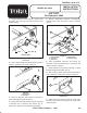
1. Using dimensions shown in figure 1, locate, mark
and drill a .391" dia. hole in left side of machine (thru
existing decal).
Figure 1
.391" dia. (2)
6.47"
1.00"
1
1. Roller pivot
Left Side Shown
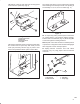
2. Affix a danger decal over existing decal on side of
machine, positioning as shown in figure 2.
Figure 2
1
1. Danger decal
2. Roller pivot
2
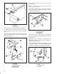
3. Secure a capscrew and locknut to rear hole in
guard assembly as shown in figure 3.
4. Mount guard assembly and pivot spacer to left side
of machine with a capscrew and locknut (Fig. 3).
Capscrew in guard to be positioned below frame.
5. Remove flangehead capscrew and flangenut
securing front of left roller pivot to side of machine
(Fig. 3).
Figure 3
1. Guard assembly
2. Pivot spacer
3. Roller pivot
1
2
4
3
4. Spring bracket
5. Extension spring
5
6. Using flangehead capscrew and flange nut
removed, mount a spring bracket to roller pivot and
frame as shown in figure 3.
7. Hook extension spring (shorter spring) to spring
bracket and guard assembly (Fig. 3).
8. Affix a waring decal, above guard assembly on
side of machine, positioning as shown in figure 4.
Figure 4
1
1. Warning decal
9. Using dimensions shown in figure 5, locate, mark
and drill a .156" dia. hole in flange on top (front) of left
roller side plate.